728x90

Showing posts with label Oscillator. Show all posts

Wednesday, December 27, 2023

PIC16F887 DHT-11 LCD Example Using XC8

DHT11 converts the surrounding temperature and humidity to serial digital data for any micro-processor. It uses only one serial data wire. It able to convert between 0 and 50 degree Celsius in temperature, and 0 to 90RH for humidity. It's suitable for air conditioning system, agricultural application, etc.

PIC16F887 DHT-11 LCD Example Using XC8
DHT-11 Sensor

PIC16F887 DHT-11 LCD Example Using XC8
Prototyping Board

It contains 5 bytes (40 bits) of digital data. They are 1 byte of humidity, 1 byte of temperature, and 1 byte of check sum. For more information about decoding its data byte please check this post.

PIC16F887 DHT-11 LCD Example Using XC8
DTH-11 Sensor

 
PIC16F887 DHT-11 LCD Example Using XC8
TC1604A-01 16x4 Character LCD Module

In this example, I use an 8-bit PIC micro-controller PIC16F887, a DHT-11 sensor module, and a 16x2 character LCD to read and display the environmental data. I use the Microchip MPLABX IDE v6.15 and its XC8 C compiler v2.36 (free version).

  1. /*
  2.  * File: main.c
  3.  * Author: Admin
  4.  *
  5.  * Created on December 26, 2023, 9:03 PM
  6.  * PIC16F887 DHT-11 Sensor and LCD Example
  7.  * MPLABX IDE v6.15 XC8 v2.36
  8.  */
  9.  
  10. #include <xc.h>
  11. #include "config.h"
  12. #include "LCD4Bits.h"
  13. #include <stdio.h>
  14.  
  15. #define _XTAL_FREQ 8000000UL
  16.  
  17. #define DATA_PIN RD0
  18. #define DATA_DIR TRISD0
  19.  
  20. uint8_t data[5];
  21. void readDHT11(void){
  22. for(uint8_t i=0;i<5;i++) data[i]=0;
  23. DATA_DIR=0;
  24. DATA_PIN=1;
  25. __delay_ms(10);
  26. DATA_PIN=0;
  27. __delay_ms(18);
  28. DATA_PIN=1;
  29. __delay_us(30);
  30. DATA_PIN=0;
  31. DATA_DIR=1;
  32. __delay_us(10);
  33. while(DATA_PIN==0);
  34. __delay_us(10);
  35. while(DATA_PIN==1);
  36. __delay_us(10);
  37.  
  38. //Start of Transmission
  39. for(uint8_t i=0;i<5;i++) {
  40. for(uint8_t j=0;j<8;j++){
  41. __delay_us(5);
  42. while(DATA_PIN==0);
  43. __delay_us(50);
  44. if(DATA_PIN==1) { data[i]|=(1<<7-j); while(DATA_PIN==1);}
  45. }
  46. __delay_us(10);
  47. }
  48. /*CRC Calculation - the last byte data[4] is check sum*/
  49. uint8_t crc = data[0]+data[1]+data[2]+data[3];
  50. if(crc!=data[4]) {for(uint8_t i=0;i<4;i++) data[i]=0; return;}
  51. __delay_us(10);
  52. }
  53.  
  54.  
  55. void main(void) {
  56. OSCCONbits.IRCF=7;
  57. char msg[8];
  58. PORTA=0;
  59. TRISA=0;
  60. lcdInit();
  61. lcdString("Temperature:");
  62. __delay_ms(1000);
  63. while(1){
  64. readDHT11();
  65. sprintf(msg,"%2dRH",data[0]);
  66. lcdXY(1,2); lcdString(msg);
  67. sprintf(msg,"%2d%cC",data[2],223);
  68. lcdXY(8,2); lcdString(msg);
  69. __delay_ms(500);
  70. }
  71. return;
  72. }
  73.  

I use its 8MHz internal oscillator clock source leaving the XTAL1 and XTAL2 pin opened.

PIC16F887 DHT-11 LCD Example Using XC8

Dashboard

PIC16F887 DHT-11 LCD Example Using XC8

Running Program


PIC16F887 DHT-11 LCD Example Using XC8

Running Program


PIC16F887 DHT-11 LCD Example Using XC8

Simulating Program


Proteus VSM can be used for circuit design and simulation. Click here to download its source file.


Friday, November 10, 2023

PIC16F84A Simple Frequency Meter With LCD Using XC8

Frequency meter can be made using a conventional digital ICs with a big size, and complicated circuit connection. A small 8-bit micro-controller could do this job using a low level Assembly language or even a higher level C language.

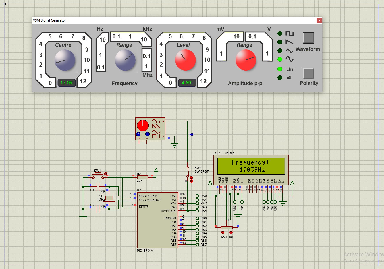
In this example, I use an 8-bit PIC16F84A micro-controller to count external TTL input pulse. The total count will update for every seconds.

PIC16F84A Simple Frequency Meter With LCD Using XC8
Simulating Program


I use RA4/T0CKI (Timer0 External Clock Input) pin to count external TTL pulse. Since Timer0 is only 8-bit wide the maximum counting is only 255 counts. So I add Timer0 Interrupt to increase the maximum counts. I use XC8 built-in delay function to create a precise 1000 ms (1 second) delay before the summation of external pulse is evaluated. A 16x2 character LCD is suitable for this example.

  1. #include <stdio.h>
  2. #include <xc.h>
  3.  
  4. #define _XTAL_FREQ 4000000UL
  5.  
  6. #include "LCD4Bits.h"
  7.  
  8. void tmr0Init(void){
  9. PORTA=0;
  10. TRISA4=1;
  11. T0CS=1;
  12. T0SE=0;
  13. PSA=1;
  14. OPTION_REGbits.PS=0;
  15. T0IE=1;
  16. GIE=1;
  17. T0IF=0;
  18. }
  19.  
  20. long TMR0H=0;
  21.  
  22. void interrupt T0_ISR(void){
  23. if(T0IF){
  24. TMR0H+=1;
  25. T0IF=0;
  26. }
  27. }
  28.  
  29. int main(void){
  30. unsigned char freq[10];
  31. uint32_t temp=0;
  32. PORTB=0;
  33. TRISB=0;
  34. lcdInit();
  35. tmr0Init();
  36. lcdXY(4,1);
  37. lcdString("PIC16F84A");
  38. lcdXY(1,2);
  39. lcdString("Frequency Meter");
  40. __delay_ms(1000);
  41. lcdCommand(CLEAR_SCREEN);
  42. __delay_ms(5);
  43. lcdXY(4,1);
  44. lcdString("Frequency:");
  45. TMR0H=0;
  46. TMR0=0;
  47. while(1){
  48. __delay_ms(1000);
  49. temp=(TMR0H<<8)+TMR0;
  50. lcdXY(6,2);
  51. sprintf(freq,"%uHz ",temp);
  52. lcdString(freq);
  53. TMR0H=0;
  54. TMR0=0;
  55. }
  56. return 0;
  57. } 

I can not test it on bread-board because this chip was burn out. And I only have some newer PIC chips. So this program can only be tested using a simulator like Proteus. We can use another PIC chip like the PIC16F628A, and CCS PICC compiler

PIC16F84A Simple Frequency Meter With LCD Using XC8
Resource Usage


This program require 69.5% of program memory, and 89.7% of data memory. Click here to download this example.


Thursday, October 7, 2021

Internal Oscillator of PIC18F1220


Introduction

Clock source of PIC18F1220 is driven from external source or internal source. Using external crystal, clocking frequency is broad but it needs additional clocking circuitry and components.

Internal Oscillator of PIC18F1220
Oscillator type

External Crystal Oscillator

External clock source are Low Power (LP), Crystal/Resonator (XT), and High Speed (HS) crystal oscillator. Its frequency ranges from 32kHz to 20MHz.

Internal Oscillator of PIC18F1220
Crystal oscillator and its capacitors value used

Internal RC Oscillator

Internal oscillator is an inside RC oscillator that can be set in program. Its frequency ranges from 31kHz to 8MHz. To use this feature, programmer need to work with PIC18F1220 configuration bits, Oscillator Control Register, and Oscillator Tuning Register.

Internal Oscillator of PIC18F1220
Clock diagram of PIC18F1220

Using internal oscillator save components requirement, and on-board design space.

Setting Up in Program

Setting configuration bits of PIC18F1220 is a priority for internal oscillator.

Configuration Bits

There are up to 13 configuration registers in PIC18F1220. However CONFIGH1H (address 300001h) contains setting for internal oscillator.

Internal Oscillator of PIC18F1220
CONFIG1H Configuration Register

However in XC8 programmer use “#pragma config” directive. Programmer can select only internal oscillator only, or with I/O function on RA6 and RA7.

Registers Setting

There are two registers in SFR relate to internal oscillator.

Oscillator Tuning Registers – OSCTUNE

This register make a frequency tuning of internal oscillator between its lowest frequency and its highest frequency.

Internal Oscillator of PIC18F1220
Oscillator Tuning Registers – OSCTUNE

Oscillator Control Register – OSCCON

This register set system clock mode, switch between discrete frequency of internal oscillator, and status checking.

Internal Oscillator of PIC18F1220
Oscillator Control Register – OSCCON

Programming Example

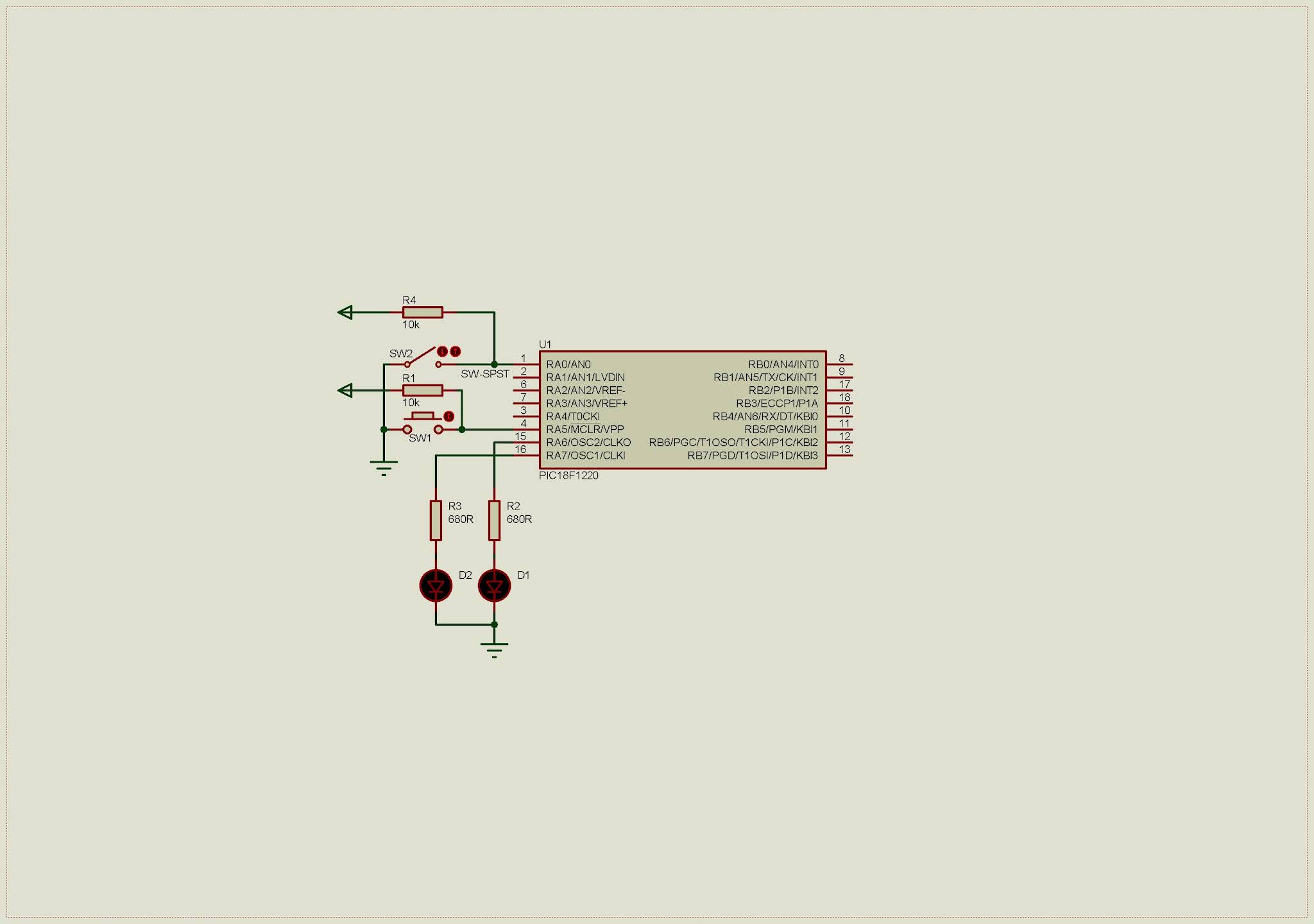
We want to test selected 4MHz internal oscillator. LED connects to RA7 blinks at a specific rate. A push button connects to RA0 toggles an output LED on RA6 whenever it’s pressed.

Schematic Diagram

Since internal oscillator is used, there is no requirement to add external crystal oscillator.

Internal Oscillator of PIC18F1220
Schematic Diagram

C Programming

Port A is multiplexed with analog input function. User needs to disable this feature to make this port as a solely digital I/O.

C

Configuration bits contain setting for this controller especially internal oscillator setting. We choose internal oscillator with I/O function on both RA6 and RA7.

C

Click here to download this programming example package.


Search This Blog

Labels

23K256 (1) 24C16B (2) 25AA010A (2) 8051 (7) 93AA46B (1) ADC (34) Analog Comparator (1) Arduino (16) ARM (13) AT89C52 (7) ATMega32 (58) ATMega644P (27) AVR (87) Bootloader (1) CCS PICC (31) Change Notify Interrupt (CNI) (2) DAC (2) DHT11 (4) Display (133) Distance Sensor (3) ds1307 (10) DS18B20 (5) ds3231 (1) ds3232 (2) dsPIC (5) dsPIC30F1010 (3) dsPIC30F2010 (5) EEPROM (5) Environment Sensor (5) ESP32 (1) esp8266 (1) Graphical LCD (2) I2C (38) ILI9341 (1) Input/Output (75) Interrupt (22) Keil (5) Keypad (16) KS0108 (2) LCD (75) LM35 (3) Master/Slave (2) MAX7221 (1) MCP23017 (8) MCP23S17 (7) MCP4921 (1) MCP4922 (2) Meter (3) MikroC (2) Motor (15) MPLABX (73) Nokia 5110 LCD (4) OLED (2) One-Wire (7) Oscillator (8) PCB (10) PCD8544 (3) PCF8574 (10) PIC (108) PIC12F (3) PIC16F628A (3) PIC16F630 (2) PIC16F716 (4) PIC16F818 (11) PIC16F818/819 (3) PIC16F84A (16) PIC16F876A (2) PIC16F877A (9) PIC16F88 (2) PIC16F887 (60) PIC18 (19) PIC18F1220 (5) PIC18F2550 (5) PIC18F4550 (12) PICKit2 (1) Pin Change Interrupt (1) PWM (12) RTC (12) SBN0064G (1) Sensor (13) SH1106 (3) Shift Register (13) Shift Registers (10) Software TWI (2) SPI (39) ST7735 (1) STM32 (11) STM32 Black Pill (1) STM32 Blue Pill (12) STM32 HAL (5) STM32CubeIDE (13) STM32F103C8T6 (9) STM32F401CCU6 (1) SysTick (4) temperature sensor (13) TFT (1) TG12864A (1) Thermometer (22) Timer/Counter (32) TM1637 (2) twi (10) UART (8) Ultrasonic (4) Voltmeter (7) WDT (1) XC16 (2) XC8 (96)