Overview
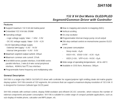
An SH1106 is a 132x64 LED display driver with controller. This chip support 8-bit 6800-series parallel interface, 8-bit 8080-series parallel interface, Serial Peripheral Interface (SPI), and Inter Integrated Circuit (I2C) bus interface. It usually come with an 1.3 inches 128x64 OLED display module with an SPI or an I2C interface.
 |
| PIC16F887 OLED Display |
Using this module with an Arduino is very popular. Some programmer creates a simple game console using this display. Arduino platform has a lot of libraries and graphic for this LCD module.
.jpg) |
| 1.3 Inches 1106 128x64 IIC OLED Module |
.jpg) |
| 1.3 Inches 1106 128x64 IIC OLED Module |
Without Arduino we can check the LCD Wiki website for programming and interfacing with this device using different micro-processor.
For full specification please check product datasheet. The LCD is mounted on a PCB with a ready to use I2C interface. Its supply voltage is 5VDC by default.Here we will use a two-wire I2C bidirectional bus interface. This module has an on-board 10kΩ pull-up resistors. Its I2C write address is 0x78 by default. This chip could handle up to 40kHz serial clock frequency. But I use only 200kHz with PIC16F887 I2C module to prevent it from being halted.
 |
| I2C System Configuration |
Using only two-wire data bus the controller can communicate with multiple devices. This I2C display is writable and readable.
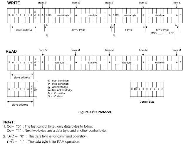
The micro-processor writes command or data to this display. It begin by an I2C start bit, device address (eg. 0x78), Acknowledge bit (A), Control Byte, Data Byte, and an I2C stop bit.
Data/Command (D/C) bit of the control byte determine between display RAM data and command as it's shown in the picture above.
Display RAM Data can also be read from this display module.
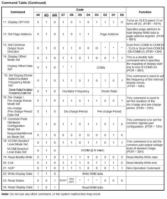
To use it properly we need to set its display commands using a command set below.
- Set Low Column Address: (00H - 0FH)
- Set Higher Column Address: (10H - 1FH)
- Set Pump voltage value: (30H - 33H)
- Set Display Start Line: (40H - 7FH)
- Set Contrast Control Register: (Double Bytes Command), The Contrast Control Mode Set (81H), Contrast Data Register Set (00H - FFH)
- Set Segment Re-map: (A0H - A1H)
- Set Entire Display OFF/ON: (A4H - A5H)
- Set Normal/Reverse Display: (A6H - A7H)
- Set Multiplex Ration: (Double Bytes Command), Multiplex Ration Mode Set: (A8H), Multiplex Ration Data Set: (00H - 3FH).
- Set DC-DC OFF/ON: (Double Bytes Command), DC-DC Control Mode Set: (ADH), DC-DC ON/OFF Mode Set: (8AH - 8BH).
- Display OFF/ON: (AEH - AFH)
- Set Page Address: (B0H - B7H)
- Set Common Output Scan Direction: (C0H - C8H)
- Set Display Offset: (Double Bytes Command), Display Offset Mode Set: (D3H), Display Offset Data Set: (00H - 3FH)
- Set Display Clock Divide Ratio/Oscillator Frequency: (Double Bytes Command), Divide Ratio/Frequency Mode Set: (D5H), Divide Ratio/Oscillator Frequency Data Set: (00H - FFH).
- Set Dis-Charge/Pre-Charge Period: (Double Bytes Command), Pre-charge Period Mode Set: (D9H), Dis-charge/Pre-charge Period Data Set: (00H - FFH)
- Set Common pads hardware configuration: (Double Bytes Command), Common Pads Hardware Configuration Mode Set: (DAH), Sequential/Alternative Mode Set: (02H - 12H).
- Set VCOM Deselect Level: (Double Bytes Command), VCOM Deselect Level Mode Set: (DBH), VCOM Deselect Level Data Set: (00H - FFH).
- Read-Modify-Write: (E0H)
- End: (EEH)
- NOP: (E3H)
- Write Display Data
- Read Status
- Read Display Data
For a fully explained text, you can check its datasheet. These command are summerized in a command table below.
 |
| Command Table 1 |
 |
| Command Table 2 |
We can see its user's manual include programming tutorial to get used to this display controller.
PIC16F887 MPLABX IDE and XC8 Programming
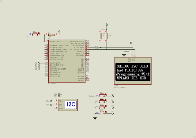
An 8-bit PIC16F887 is suitable for this display controller since it has a high speed I2C module inside. I configure this module with a clock frequency of 200kHz. The program will send a 8x16 character text to the display.
Only text fonts requires a lot of program space. To get additional fonts and graphic we can add an SPI or an I2C EEPROM or even a Flash memory to store those data.
 |
| Protues Simulation |
 |
| Running Program |
 |
| Running Program |
Click here to download its source file.
.jpg)
.jpg)

