Overview
HC-SR04 is an ultrasonic range finder. It uses sound wave traveling to find detected object distance. Its working range is between 4cm and 4m. To control and get distance data from this sensor we can use a digital circuit, or a microprocessor, or even manually by hand. Its echo output is a logic high level TTL signal with a specific period. A microprocessor's timer is used for calculating the timing signal associated with distance. For more details about using this sensor with a simple PIC16F84A micro-controller you can see this post.
 |
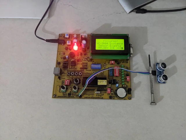
| PIC16F887 Prototyping Board |
 |
| PIC16F887 Prototyping Board |
.jpg) |
| HC-SR04 Module Front |
.jpg) |
| HC-SR04 Module Back |
MPLABX IDE and XC8 C Programming
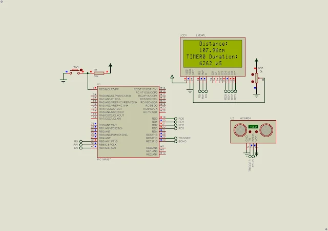
In this XC8 programming example, I use a PIC16F887 8-bit micro-controller to read distance data, and displaying its timing value with calculated distance on a 16x4 character LCD. I use Timer0 timer/counter to measure the sensor's TTL high pulse period.
 |
| Schematic and Program Simulation |
An 8MHz internal RC oscillator is used for the system. Timer0 prescaler is set to 1:2 to get a 1µs timing ticks. Since this timer module is an 8-bit timer/counter I use TIMER0 interrupt to expand its timing period. Hence it becomes a 16-bit timer with the aid of timing interrupt.
An 8-bit micro-controller is easy to program using C in MPLABX IDE and XC8 embedded C compiler from Microchip Technology. An HD44780 character LCD is very simple to interface and program. This character LCD is common operate in 4-bit data transfer mode.
The Interrupt Service Routine (ISR) for PIC micro-controller in XC8 programming is differ depends on the version of the compiler. Some time the source codes can generate error in other version. In some case, it can be build but the ISR does not work during run-time. So we will need to read its compiler user manual.
 |
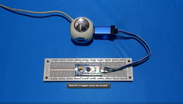
| MPLABX IDE Dashboard |
Click here to download its source file.

