Wednesday, October 7, 2020

ATMega32 SPI and Nokia 5510 LCD Interfacing

Overview

The Nokia 5510 mobile phone came with a 84x48 graphical LCD display. This display is a  monochrome dot matrix with controller PCD8544 from NXP semiconductor. The PCD8544 interfaces to the MCU using the high speed SPI communication interface.

A Nokia 5510 LCD module from an Ali Express Store.

This eight-pins module has its pin function as descripted below:

  1. VCC - Positive supply voltage (from 2.7 V to 3.3 V)
  2. GND - Ground connection
  3. SCE - Chip Select (active low)
  4. RST - Reset (active low)
  5. D/C - Data/Command mode ( low for command and high for data)
  6. DIN - SPI MOSI
  7. SCLK - SPI serial clock
  8. LED - LED backlight supplies at 3.3V maximum voltage
The LCD command is the instruction that force the internal setup - for example choosing the display bias, or selecting between the horizonal and vertical orientation. 

The LCD data is graphical data that will show on the output screen of the LCD module.

LCD Command

Writing the commands to the controller is the first thing to set up the display before displaying the text or other graphical data on the LCD screen. The MCU must clear the D/C pin with a specific SPI instruction to command the LCD controller. The picture below shows all the command from the device datasheet.

Commands for the PCD8544 matrix LCD controller

Within those byte of instruction there are some bits to explain that list below.

Explanations of each bit

There are many details due to the device's specification. Here I descript only some basic and most used commands.
The display can be selected to show in a horizontal or a vertical mode. The screen could be,
  1. displays blank
  2. operates in normal mode
  3. displays all segments
  4. display an inverse video
The controller could be set to power down or become active up to the MCU command to the controller. The display bias voltage set the LCD contrast. It's configured in software using the LCD command, and more other stuffs.

The SPI communication to this controller work in two modes - a single byte transmission and a multiple bytes transmission.

ATMega32 AVR Interfacing and Programming With The Nokia 5510 LCD Module

For an introductory example using this device, I follow the recommended instruction created by the LCD controller's vendor to make a proper operation for this device.

The LCD module is a Spark Fun Nokia 5510 module I bought from E Bay. With this simple example the display show only text and displaying the time since it's powered up.

The displaying text is a set of font I get from the Arduino play ground website.

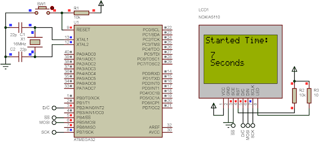
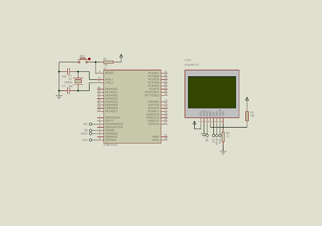
Schematic

ATMega32 SPI and Nokia 5510 LCD Interfacing
Schematic Diagram

C Source Code In Atmel Studio 7


Click here to download the zip file of this working example. The simulation result could be seen below.

ATMega32 SPI and Nokia 5510 LCD Interfacing
Simulation Result

Search This Blog

Labels

25AA010A (1) 8051 (7) 93AA46B (1) ADC (30) Analog Comparator (1) Arduino (15) ARM (6) AT89C52 (7) ATMega32 (54) AVR (57) CCS PICC (28) DAC (1) DHT11 (2) Display (105) Distance Sensor (3) DS18B20 (3) dsPIC (2) dsPIC30F1010 (2) EEPROM (5) Environment Sensor (4) esp8266 (1) I2C (29) Input/Output (67) Interrupt (19) Keil (5) Keypad (10) LCD (46) Master/Slave (1) MAX7221 (1) MCP23017 (5) MCP23S17 (4) Meter (3) MikroC (2) Motor (15) MPLABX (66) Nokia 5110 LCD (3) OLED (2) One-Wire (6) Oscillator (8) PCB (6) PCD8544 (3) PCF8574 (5) PIC (107) PIC12F (2) PIC16F628A (2) PIC16F630 (1) PIC16F716 (3) PIC16F818 (10) PIC16F818/819 (2) PIC16F84A (15) PIC16F876A (1) PIC16F877A (9) PIC16F88 (1) PIC16F887 (60) PIC18 (19) PIC18F1220 (4) PIC18F2550 (3) PIC18F4550 (12) PWM (11) RTC (8) Sensor (10) SH1106 (1) Shift Register (11) Shift Registers (2) SPI (24) STM32 (6) STM32 Blue Pill (6) STM32CubeIDE (6) STM32F103C8T6 (6) SysTick (3) temperature sensor (11) Thermometer (21) Timer/Counter (30) TM1637 (2) UART (7) Ultrasonic (4) Voltmeter (7) WDT (1) XC16 (2) XC8 (94)