728x90

728x90

Showing posts with label PIC18. Show all posts

Thursday, October 7, 2021

Internal Oscillator of PIC18F1220


Introduction

Clock source of PIC18F1220 is driven from external source or internal source. Using external crystal, clocking frequency is broad but it needs additional clocking circuitry and components.

Internal Oscillator of PIC18F1220
Oscillator type

External Crystal Oscillator

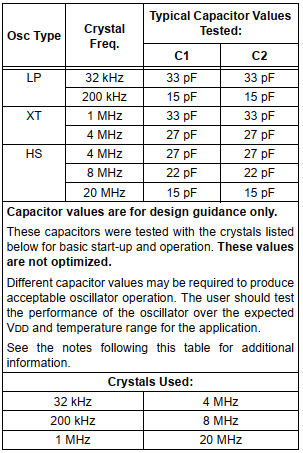
External clock source are Low Power (LP), Crystal/Resonator (XT), and High Speed (HS) crystal oscillator. Its frequency ranges from 32kHz to 20MHz.
Internal Oscillator of PIC18F1220
Crystal oscillator and its capacitors value used

Internal RC Oscillator

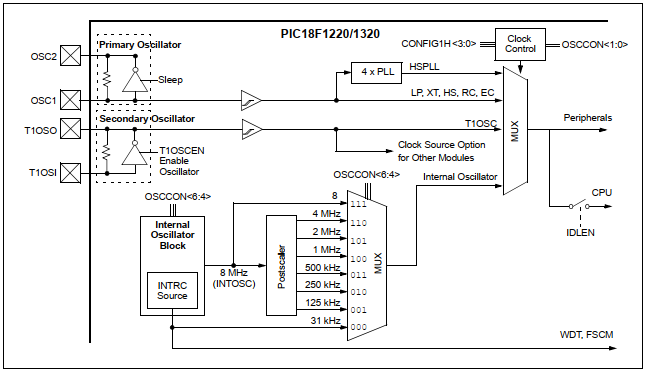
Internal oscillator is an inside RC oscillator that can be set in program. Its frequency ranges from 31kHz to 8MHz. To use this feature, programmer need to work with PIC18F1220 configuration bits, Oscillator Control Register, and Oscillator Tuning Register.
Internal Oscillator of PIC18F1220
Clock diagram of PIC18F1220

Using internal oscillator save components requirement, and on-board design space.

Setting Up in Program

Setting configuration bits of PIC18F1220 is a priority for internal oscillator.

Configuration Bits

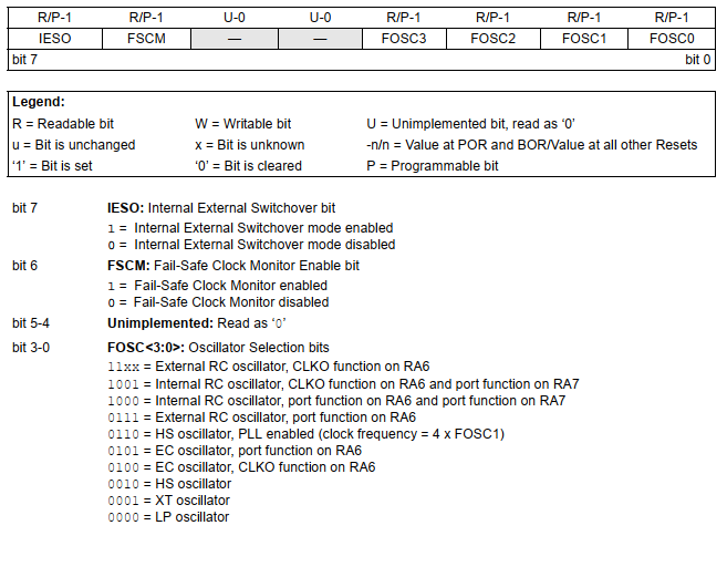
There are up to 13 configuration registers in PIC18F1220. However CONFIGH1H (address 300001h) contains setting for internal oscillator.
Internal Oscillator of PIC18F1220
CONFIG1H Configuration Register

However in XC8 programmer use “#pragma config” directive. Programmer can select only internal oscillator only, or with I/O function on RA6 and RA7.

Registers Setting

There are two registers in SFR relate to internal oscillator.

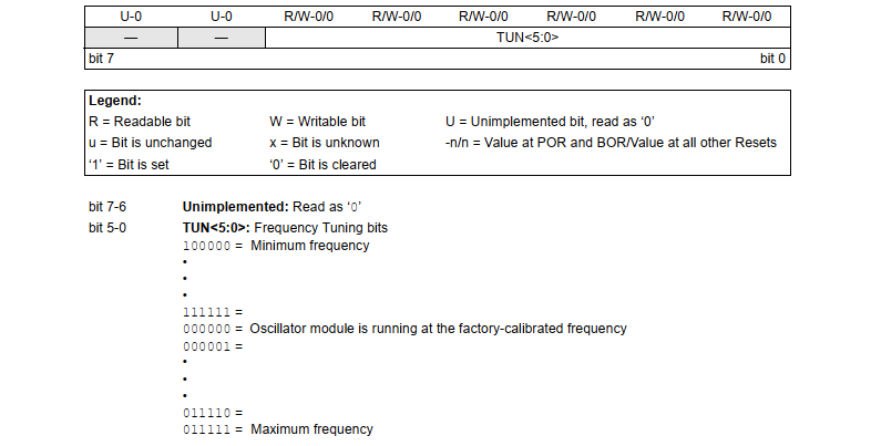
Oscillator Tuning Registers – OSCTUNE

This register make a frequency tuning of internal oscillator between its lowest frequency and its highest frequency.
Internal Oscillator of PIC18F1220
Oscillator Tuning Registers – OSCTUNE

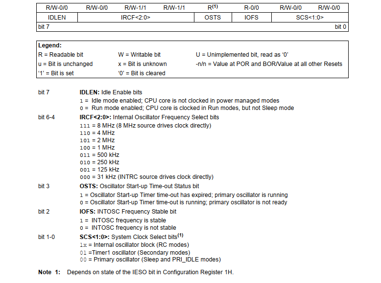
Oscillator Control Register – OSCCON

This register set system clock mode, switch between discrete frequency of internal oscillator, and status checking.
Internal Oscillator of PIC18F1220
Oscillator Control Register – OSCCON

Programming Example

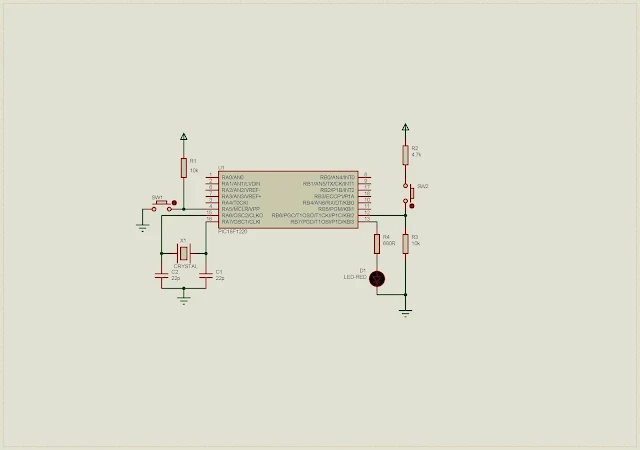
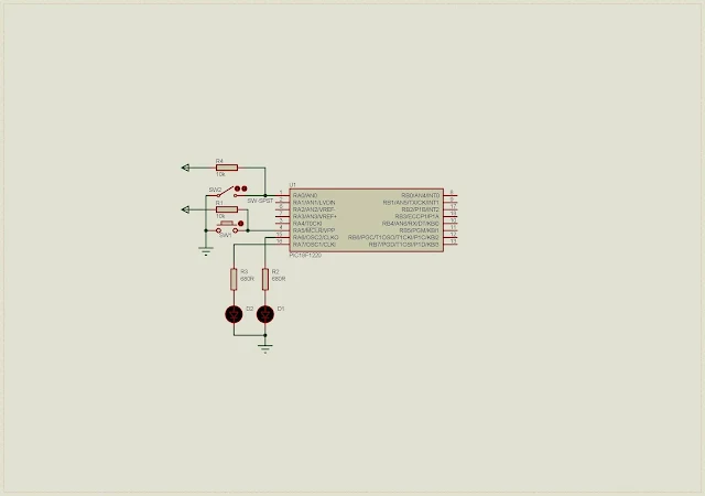
We want to test selected 4MHz internal oscillator. LED connects to RA7 blinks at a specific rate. A push button connects to RA0 toggles an output LED on RA6 whenever it’s pressed.

Schematic Diagram

Since internal oscillator is used, there is no requirement to add external crystal oscillator.
Internal Oscillator of PIC18F1220
Schematic Diagram

C Programming

Port A is multiplexed with analog input function. User needs to disable this feature to make this port as a solely digital I/O.

C

Configuration bits contain setting for this controller especially internal oscillator setting. We choose internal oscillator with I/O function on both RA6 and RA7.

C

Click here to download this programming example package.


Wednesday, September 29, 2021

Using Digital I/O of PIC18F1220


Introduction

PIC18F1220 has two 8-bit digital I/O ports – Port A and Port B. They are bi-directional readable and writable. Their data directions are controlled by their TRIS registers.

Using Digital I/O of PIC18F1220

Port A

Port A data direction is controlled by TRISA. Setting this registers allowing this port to accept input data, otherwise outputting digital data.

PORTA is considered as an input buffer. LATA is an output buffer. These two registers must be cleared before configuring its data direction.

Using Digital I/O of PIC18F1220
Pin diagram of PIC18F1220

Port B

Port B data direction is controlled by TRISB. Setting this register allowing this port to accept input data, otherwise outputting digital data.

PORTB is considered as an input buffer. LATB is an output buffer. These two registers must be cleared before configuring its data direction.

Port B Programming Example

Since Port A and Port B are multiplexed with analog input function. I decided to select some pin of Port B that are solely digital I/O pin.

Schematic Diagram

RB6 of Port B is selected as a digital input pin connecting to a push button. RB7 connects to an output LED. Whenever push button is pressed the controller toggle output LED.

Using Digital I/O of PIC18F1220
Schematic Diagram

External crystal oscillator has a frequency of 4MHz.

MPLABX XC8 Programming

This introductory tutorial is written in XC8 in MPLABX IDE. Overall program made of a dozen of lines.

C

Configuration bit of PIC18F1220 putted separately in “config.h” file.

C

Click here to download zip file of this programming example.

320x50

Search This Blog

Labels

25AA010A (1) 8051 (7) 93AA46B (1) ADC (30) Analog Comparator (1) Arduino (15) ARM (6) AT89C52 (7) ATMega32 (57) AVR (58) CCS PICC (28) DAC (1) DHT11 (2) Display (106) Distance Sensor (3) DS18B20 (3) dsPIC (3) dsPIC30F1010 (3) dsPIC30F2010 (1) EEPROM (5) Environment Sensor (4) esp8266 (1) I2C (29) Input/Output (68) Interrupt (19) Keil (5) Keypad (10) LCD (48) Master/Slave (1) MAX7221 (1) MCP23017 (5) MCP23S17 (4) Meter (3) MikroC (2) Motor (15) MPLABX (73) Nokia 5110 LCD (3) OLED (2) One-Wire (6) Oscillator (8) PCB (10) PCD8544 (3) PCF8574 (5) PIC (108) PIC12F (3) PIC16F628A (3) PIC16F630 (2) PIC16F716 (4) PIC16F818 (11) PIC16F818/819 (3) PIC16F84A (16) PIC16F876A (2) PIC16F877A (9) PIC16F88 (2) PIC16F887 (60) PIC18 (19) PIC18F1220 (5) PIC18F2550 (5) PIC18F4550 (12) PICKit2 (1) PWM (11) RTC (9) Sensor (11) SH1106 (1) Shift Register (11) Shift Registers (3) SPI (24) STM32 (6) STM32 Blue Pill (6) STM32CubeIDE (6) STM32F103C8T6 (6) SysTick (3) temperature sensor (11) Thermometer (21) Timer/Counter (31) TM1637 (2) UART (7) Ultrasonic (4) Voltmeter (7) WDT (1) XC16 (2) XC8 (96)

tyro-728x90