728x90

728x90

Showing posts with label ATMega32. Show all posts

Sunday, July 13, 2025

A DIY ATMega32 Prototype Board

Overview

AVR micro-controller is a popular embedded controller for electronic students, engineers and hobbyists. Making a PCB for for micro-controller is exiting stuff for novice electronic practicing. It's is hard at first time but we can easily use it for firmware and circuit testing for later on.

A DIY ATMega32 Prototype Board 

A DIY ATMega32 Prototype Board

A DIY ATMega32 Prototype Board

A DIY ATMega32 Prototype Board

A DIY ATMega32 Prototype Board


I have some components I left a long time ago. So I designed my own test board for 40-pin AVR microcontrollers. I have ATMega644, ATMega32 and ATMega16 in my project box. I also have some USB PIC microcontroller, PIC18F2550. It can be use to make a DIY PICKit2 programmer that able to program any AVR microcontroller using AVRdude IDE. This software is very user-friendly. 

Some AVR micro-controller users prefer a USBasp or an FTDI chip with AVRdude to program this these chips. But currently I don't have them at my workshop. 

Schematic 

I use Protues VSM since it's easy to use for circuit and PCB design. I put some blocks on this board,

  1. A PICKit2 programmer and AVR ISP header
  2. A On-board 12VDC to 5VDC regulator
  3. A RS-232 to TTL converter
  4. A Reset button and external crystal oscillator
  5. Three buttons for ATMega32 external interrupts
  6. LED(s) with DIP switch connects to PORTC
  7. SPI header
  8. Two potentiometers for ADC input
  9. DIP switch for ADC configuration
  10. A DS1207 I2C RTC 
  11. A  40-pin ZIF socket for ATMega32, ATMega16, etc.

 The pictures below are its circuit diagram.
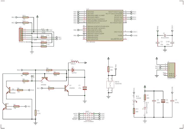
A DIY ATMega32 Prototype Board
Schematic Sheet #1

A DIY ATMega32 Prototype Board
Schematic Sheet #2

A DIY ATMega32 Prototype Board
Schematic Sheet #3

 It contains three A4-size sheets.

Printed Circuit Board (PCB)

This PCB is quite large (173.7 x 111.2mm(6.84 x 4.38 inches). We can fabricate it by hand using a simple tone transfer paper method because it contain a dozen of wire jumpers on top copper layer.

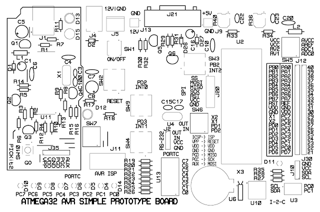
A DIY ATMega32 Prototype Board
Top Copper Layer

A DIY ATMega32 Prototype Board
Bottom Copper Layer

 I you prefer a simple tone transfer method, use the patterns below.

A DIY ATMega32 Prototype Board
Top Copper Layer

A DIY ATMega32 Prototype Board
Bottom Copper Layer

A DIY ATMega32 Prototype Board
Top Silk Layer

A DIY ATMega32 Prototype Board
Bottom Resist Layer

 Some PCB fabrication could fabricate it for around 40USD.

However I made the earlier version of this board by hand using a simple toner transfer method and and FR-4 copper clad board. I use ferric chloride acid to etch the copper clad. It's very low cost and fast. 

A DIY ATMega32 Prototype Board

A DIY ATMega32 Prototype Board

A DIY ATMega32 Prototype Board

A DIY ATMega32 Prototype Board

A DIY ATMega32 Prototype Board

A DIY ATMega32 Prototype Board

A DIY ATMega32 Prototype Board

A DIY ATMega32 Prototype Board

A DIY ATMega32 Prototype Board


 Click here to download this PCB project.


Friday, July 22, 2022

Atmega32 EEPROM Programming Example

There are two main memory spaces in Atmega32 microcontroller, the Data Memory and the Program Memory space. An additional EEPROM Memory is useful for data storage. It's non-volatile. Hence this controller has three memory space. They are linear and regular.

EEPROM memory space contains up to 1024 bytes of data. It's separated from data space. It's single byte readable and writable. It endurance is up to 100,000 write/erase cycles. Its access time is around 8.5ms for the internal RC clock of 1MHz.

During the device is in power-down sleep mode, the EEPROM write operation still continuous. But it's not completely power down. So the the programmer must verify the EEPROM first before setting the device to entirely power-down mode.

EEPROM corruption can occur whenever the supply voltage is too low, that the instruction execution is incorrect. We can prevent it by enabling the internal Brown-out Detector (BOD). If the BOD can not help ,we can add an additional VCC reset Protection circuit. 

For low level programming like the Assembly language, the programmer must use the I/O and Peripheral Register. However in C programming for the AVR it's invisible for the programmer.

There are some registers that we have to use before accessing the EEPROM memory.

Atmega32 EEPROM Programming Example
The EEPROM Address Register – EEARH and EEARL
The address register is a 16-bit pair. But it has only 10-bit in use. So it's 10-bit (1024) address. The user can access up to 1024 bytes of EEPROM memory.

Atmega32 EEPROM Programming Example
The EEPROM Data Register – EEDR

The data register is single byte read/write.

Atmega32 EEPROM Programming Example
The EEPROM Control
Register – EECR

This memory contains,

  • Bits 7..4 – Reserved Bits
  • Bit 3 – EERIE: EEPROM Ready Interrupt Enable
  • Bit 2 – EEMWE: EEPROM Master Write Enable
  • Bit 1 – EEWE: EEPROM Write Enable
  • Bit 0 – EERE: EEPROM Read Enable

For AVR Lib-C for AVR device, we don't need to care about these registers. the programmer can use the eeprom.h library, and call its read and write function to access the EEPROM memory.

In this programming example we will use all these registers. The example below will show a simple way to access the internal EEPROM.

Atmega32 EEPROM Programming Example

Program Simulation

The controller will read and write the internal EEPROM data. The data will display on PortC.

  1. /*
  2.  * m32Eeprom.c
  3.  *
  4.  * Created: 7/20/2022 6:43:00 PM
  5.  * Author : desktop
  6.  */
  7.  
  8. #include <avr/io.h>
  9.  
  10. /*Write button connects to PD6*/
  11. #define writeButton ((PIND&0x40)==0)
  12. /*Read button connects to PD7*/
  13. #define readButton ((PIND&0x80)==0)
  14.  
  15. /*EEPROM Write Function*/
  16. void eepromWrite(unsigned int addr,unsigned char dat){
  17. /*Wait for completion of previous write*/
  18. while(EECR&(1<<EEWE));
  19. /*Set up address and data registers*/
  20. EEAR=addr;
  21. EEDR=dat;
  22. /*Write logical 1 to EEMWE*/
  23. EECR|=(1<<EEMWE);
  24. /*Start eeprom write by setting EEWE*/
  25. EECR|=(1<<EEWE);
  26. }
  27.  
  28. /*EEPROM Read Function*/
  29. unsigned char eepromRead(unsigned int addr){
  30. /*Wait for completion of previous write*/
  31. while(EECR&(1<<EEWE));
  32. /*Set up address register*/
  33. EEAR=addr;
  34. /*Start eeprom read by writing EERE*/
  35. EECR|=(1<<EERE);
  36. /*Return data from data register*/
  37. return EEDR;
  38. }
  39.  
  40. int main(void)
  41. {
  42. /*PORTC Output*/
  43. DDRC=0xFF;
  44. /*PA0...PA3 Input*/
  45. DDRA=0xF0;
  46. /*PORTB Input*/
  47. DDRB=0x00;
  48. /*Turn on porta and portb high*/
  49. PORTA=0x0F;
  50. PORTB=0xFF;
  51. /*Turn on PD6 and PD7*/
  52. PORTD=(1<<6)|(1<<7);
  53. while (1)
  54. {
  55. /*eeprom read task*/
  56. if (readButton)
  57. {
  58. /*Wait until the button released*/
  59. while(readButton);
  60. PORTC=eepromRead(PINA);
  61. }
  62. /*eeprom write task*/
  63. if (writeButton)
  64. {
  65. /*Wait until the button released*/
  66. while(writeButton);
  67. eepromWrite(PINA,PINB);
  68. }
  69. }
  70. }
  71.  
  72.  

Click here to download its source file.

Atmega32 EEPROM Programming Example
Schematic

PortA is used for address input. We use only four bits that contain up to 16 addresses.  PortB is used for data input for internal EEPROM writing. Write button connect to PD6 pin while read button connect to PD7 pin. PortC connects to a bar graph LED to display the data reading from internal EEPROM.


If you want a standard PCB for ATMega32 micro-controller, you can order my AVR Microcontroller project from PCBWay with a reasonable price. Click here to get a free $5 credit for new account.


Saturday, July 9, 2022

Atmega32 Timer/Counter1 in Counter Mode

The Timer/Counter1 module of Atmega32 is able to count external pulse. It has a 16-bit counter/timer registers pair, TCNT1H and TCNT1L. We need to select its clock source of the Timer/Counter1 Control Register B - TCCR1B to allow this module working in external event counting mode. It work in two clock transitions, falling edge and rising edge. The clock source must be point to T1 (PB1) pin.

Atmega32 Timer/Counter1 in Counter Mode
Running program in Proteus Simulator

It also have a pre-scaler to divide a number of input clock pulse. Basically I will need only the TCCR1B, TCNT1H, and TCNT1L register to make this module operate in external counting mode.

  • Timer/Counter1 Control Register B - TCCR1B

Atmega32 Timer/Counter1 in Counter Mode

Timer/Counter1 Control Register B - TCCR1B

I need to select clock select bits to allow it to work in counter mode, with a rising edge of external clock.

Atmega32 Timer/Counter1 in Counter Mode
Clock Select Bit Description

I choose the "External clock source on T1 pin. Clock on rising edge". So CS12, CS11, and CS10 will set.

  • Timer/Counter1 - TCNT1H and TCNT1L Register 

Atmega32 Timer/Counter1 in Counter Mode
Timer/Counter1 – TCNT1H and TCNT1L Registers

This register composes of two 8-bit registers pair, TCNT1H and TCNT1L. They are readable and writable.

In this example, I make a counting system that could count up to 10000 before it rolls down. Since this register is 16-bit it maximum value is 65536 values. But it's not necessary here.

  1. /*
  2.  * m32Counter1MuxDisplay.c
  3.  *
  4.  * Created: 7/9/2022 6:10:41 PM
  5.  * Author : aki-technical
  6.  */
  7.  
  8. #include <avr/io.h>
  9.  
  10. #define F_CPU 4000000UL
  11. #include <util/delay.h>
  12.  
  13. int main(void)
  14. {
  15. int temp;
  16. /*Common Cathode Display*/
  17. unsigned char displayData[10]={0x3F,0x06,0x5B,0x4F,
    0x66,0x6D,0x7D,0x07,0x7F,0x6F};
  18. /*PortB and PortD Output*/
  19. DDRC=0xFF;
  20. DDRD=0xFF;
  21. /*Select T1 Clock in, rising edge*/
  22. TCCR1B|=(1<<CS12)|(1<<CS11)|(1<<CS10);
  23. /*Clear Timer/Counter1*/
  24. TCNT1H=0;
  25. TCNT1L=0;
  26. while (1)
  27. {
  28. /*Read the 16-bit counter registers*/
  29. temp=(TCNT1H<<8)+TCNT1L;
  30. /*Reset if it reaches 10000*/
  31. if (temp>9999)
  32. {
  33. temp=0;
  34. TCNT1H=0;
  35. TCNT1L=0;
  36. }
  37.  
  38. /*Display processing*/
  39. PORTD=0x00;
  40. PORTC=displayData[temp/1000];
  41. PORTD=0x01;
  42. _delay_ms(5);
  43.  
  44. PORTD=0x00;
  45. PORTC=displayData[(temp%1000)/100];
  46. PORTD=0x02;
  47. _delay_ms(5);
  48.  
  49. PORTD=0x00;
  50. PORTC=displayData[(temp%100)/10];
  51. PORTD=0x04;
  52. _delay_ms(5);
  53.  
  54. PORTD=0x00;
  55. PORTC=displayData[temp%10];
  56. PORTD=0x08;
  57. _delay_ms(5);
  58. }
  59. }
  60.  
  61.  

 Click here to download its source file.

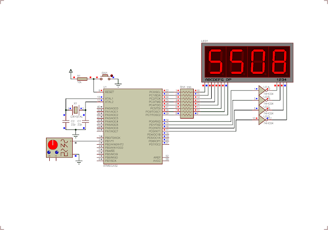
Atmega32 Timer/Counter1 in Counter Mode
Schematic


Sunday, June 19, 2022

Making a Simple Free Running Timer with Multiplexing Display using Atmega32

In previous post, I made a simple multiplexing display example using a two-digit SSD. In this example, I gonna make a free running timer two a two-digit multiplexing seven-segment display. It will start counting from 0 to 999 seconds before it reset by itself.

Making a Simple Free Running Timer with Multiplexing Display using Atmega32
Program simulation

The display is driven by delay function. Each digits are activated for only 5ms. I use Timer/Counter 0 to create timing tick.

The CPU clock is 4MHz. Clock period is,

1/4000000MHz =  250 nano seconds, or 0.00000025 second.

Timer 0 prescaler is Fosc/1024. So its Timer/Counter 0 period is,

0.00000025 second * 1024 = 256 micro seconds, or 0.000256 second.

The 8-bit TCNT0 register can store counting value up to 256. So the TOV0 occurs every,

256*0.000256 second = 0.065536 second.

To get a one second timing, I need to make a calculation of one second count. That is,

1 second count = (1 second)/(0.065536 second) = 15 counts.

Finally after the 15 counts, I will get a one-second time. Then I will need to reset the counter variable.

  1. /*
  2.  * m32Mux2Counting.c
  3.  *
  4.  * Created: 6/19/2022 3:36:14 PM
  5.  * Author : aki-technical
  6.  */
  7.  
  8. #include <avr/io.h>
  9.  
  10. /*Delay function*/
  11. #define F_CPU 4000000UL
  12. #include <util/delay.h>
  13.  
  14. int main(void)
  15. {
  16. unsigned char temp=0,cnt=0;
  17. /*Common Cathode Display*/
  18. unsigned char displayData[10]={0x3F,0x06,0x5B,0x4F,0x66,0x6D,0x7D,0x07,0x7F,0x6F};
  19. /*PortB and PortD Output*/
  20. DDRC=0xFF;
  21. DDRD=0xFF;
  22. /*Select Fclk/1024*/
  23. TCCR0|=(1<<CS02)|(1<<CS00);
  24. /*Clear TOV0 flag*/
  25. TIFR|=(1<<TOV0);
  26. /*Clear Counter*/
  27. TCNT0=0;
  28. while (1)
  29. {
  30. /*Multiplexing Display Process*/
  31. PORTD=0x00;
  32. PORTC=displayData[temp/10];
  33. /*Turn On Digit 1*/
  34. PORTD=0x01;
  35. /*Activate for 5ms*/
  36. _delay_ms(5);
  37.  
  38. PORTD=0x00;
  39. PORTC=displayData[temp%10];
  40. /*Turn On Digit 2*/
  41. PORTD=0x02;
  42. /*Activate for 5ms*/
  43. _delay_ms(5);
  44.  
  45. /*TOV0 occurs for every 0.065536 second*/
  46. if ((TIFR)&&(1<<TOV0))
  47. {
  48. cnt++;
  49. TIFR|=(1<<TOV0);
  50. }
  51.  
  52. /*One second is equal to 15 counts*/
  53. if (cnt>=15)
  54. {
  55. temp++;
  56. cnt=0;
  57. }
  58. /*Check if it is greater than 99 seconds*/
  59. if (temp>99)
  60. {
  61. temp=0;
  62. }
  63. }
  64. }
  65.  
  66.  

Click here to download its source file.

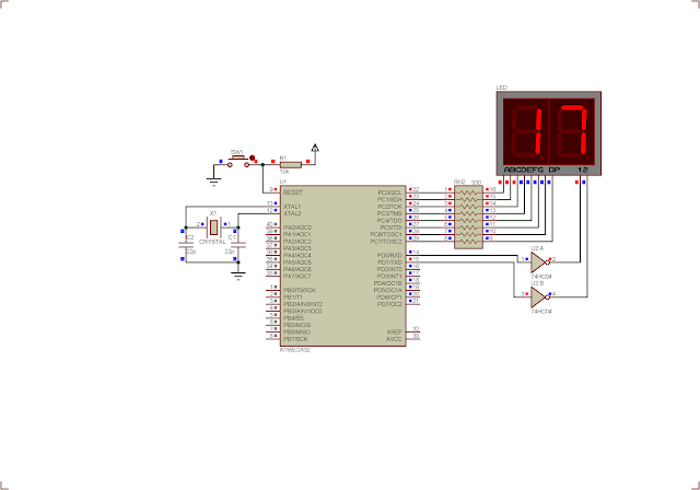
Making a Simple Free Running Timer with Multiplexing Display using Atmega32
Schematic Diagram
 

320x50

Search This Blog

Labels

25AA010A (1) 8051 (7) 93AA46B (1) ADC (30) Analog Comparator (1) Arduino (15) ARM (6) AT89C52 (7) ATMega32 (57) AVR (58) CCS PICC (28) DAC (1) DHT11 (2) Display (106) Distance Sensor (3) DS18B20 (3) dsPIC (3) dsPIC30F1010 (3) dsPIC30F2010 (1) EEPROM (5) Environment Sensor (4) esp8266 (1) I2C (29) Input/Output (68) Interrupt (19) Keil (5) Keypad (10) LCD (48) Master/Slave (1) MAX7221 (1) MCP23017 (5) MCP23S17 (4) Meter (3) MikroC (2) Motor (15) MPLABX (73) Nokia 5110 LCD (3) OLED (2) One-Wire (6) Oscillator (8) PCB (10) PCD8544 (3) PCF8574 (5) PIC (108) PIC12F (3) PIC16F628A (3) PIC16F630 (2) PIC16F716 (4) PIC16F818 (11) PIC16F818/819 (3) PIC16F84A (16) PIC16F876A (2) PIC16F877A (9) PIC16F88 (2) PIC16F887 (60) PIC18 (19) PIC18F1220 (5) PIC18F2550 (5) PIC18F4550 (12) PICKit2 (1) PWM (11) RTC (9) Sensor (11) SH1106 (1) Shift Register (11) Shift Registers (3) SPI (24) STM32 (6) STM32 Blue Pill (6) STM32CubeIDE (6) STM32F103C8T6 (6) SysTick (3) temperature sensor (11) Thermometer (21) Timer/Counter (31) TM1637 (2) UART (7) Ultrasonic (4) Voltmeter (7) WDT (1) XC16 (2) XC8 (96)

tyro-728x90