Learn To Write Code For 8051, Arduino, AVR, dsPIC, PIC, STM32 ARM Microcontroller, etc.
Coding Embedded Controller With C/C++.
Printed Circuit Board (PCB) Project For Electronics Hobbyists.
Frequency meter can be made using a conventional digital ICs with a big size, and complicated circuit connection. A small 8-bit micro-controller could do this job using a low level Assembly language or even a higher level C language.
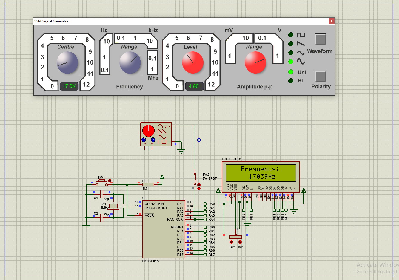
In this example, I use an 8-bit PIC16F84A micro-controller to count external TTL input pulse. The total count will update for every seconds.
Simulating Program
I use RA4/T0CKI (Timer0 External Clock Input) pin to count external TTL pulse. Since Timer0 is only 8-bit wide the maximum counting is only 255 counts. So I add Timer0 Interrupt to increase the maximum counts. I use XC8 built-in delay function to create a precise 1000 ms (1 second) delay before the summation of external pulse is evaluated. A 16x2 character LCD is suitable for this example.
#include <stdio.h>
#include <xc.h>
#define _XTAL_FREQ 4000000UL
#include "LCD4Bits.h"
void tmr0Init(void){
PORTA=0;
TRISA4=1;
T0CS=1;
T0SE=0;
PSA=1;
OPTION_REGbits.PS=0;
T0IE=1;
GIE=1;
T0IF=0;
}
long TMR0H=0;
void interrupt T0_ISR(void){
if(T0IF){
TMR0H+=1;
T0IF=0;
}
}
int main(void){
unsignedchar freq[10];
uint32_t temp=0;
PORTB=0;
TRISB=0;
lcdInit();
tmr0Init();
lcdXY(4,1);
lcdString("PIC16F84A");
lcdXY(1,2);
lcdString("Frequency Meter");
__delay_ms(1000);
lcdCommand(CLEAR_SCREEN);
__delay_ms(5);
lcdXY(4,1);
lcdString("Frequency:");
TMR0H=0;
TMR0=0;
while(1){
__delay_ms(1000);
temp=(TMR0H<<8)+TMR0;
lcdXY(6,2);
sprintf(freq,"%uHz ",temp);
lcdString(freq);
TMR0H=0;
TMR0=0;
}
return0;
}
I can not test it on bread-board because this chip was burn out. And I only have some newer PIC chips. So this program can only be tested using a simulator like Proteus. We can use another PIC chip like the PIC16F628A, and CCS PICC compiler.
Resource Usage
This program require 69.5% of program memory, and 89.7% of data memory. Click here to download this example.
The ADC module of PIC18F4550 could read an analog input voltage up to 5 V DC with some DC offset. However, the outside analog voltage fed to the ADC could be greater than 5 V DC by adding a simple voltage divider circuit.
The voltage divider circuit is very simple, built by two resistors in this case. The output voltage from the divider circuit is smaller than the input according to the dividing factor. The factor created by picking up a different resistances of the selected's. The designer may decide and take a little math calculation using voltage divider theorem to get a specific division factor.
CCS PICC have a ready to use example, demonstrating the technique of using timer 1 external pulses counting to make a 50 MHz frequency meter.
The ex_freq.c explained the the process of making frequency meter using timer 1 of PIC16F877 with a one second delay. The output data is presented in serial terminal.
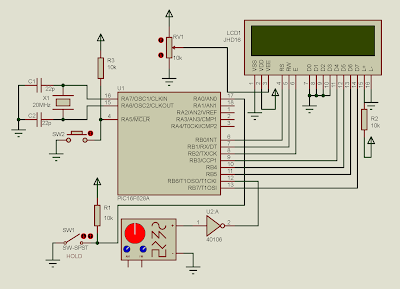
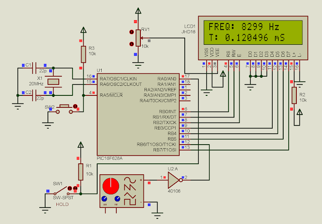
We can use timer 1 of PIC16F628A to count external digital input pulses. With this advantage, we can make a simple frequency meters, measuring the number of pulses per second.
In this example, I switch the CPU to PIC16F628A with the same build-in timer 1. A 16x2 character LCD uses to present the frequency and period.
PIC16F628A supplied at +5V, clocks at 20 MHz.
Digital Clock pulse feds into pin RB6 Timer 1 Clock In.
SW1 hold the current frequency/period Value,
when shorted to ground
C Source code and simulation file could be download here: