Wednesday, February 17, 2021

Start To Blink PIC18F4550 Using CCS PICC

Overview Of PIC18F4550

PIC18F4550 is an 8-bit PICMicro built with a USB peripheral inside.  It could clock up to 48 MHz to full fill its USB hardware requirements. The program memory size is 16384 words. It temporary memory SRAM is 2048 KB with an auxiliary non-volatile memory of 256 Bytes.

By selecting its 40-pin DIP package, the digital I/O ports available up to five ports with 35 usable inputs outputs. 

A stable direct current voltage source powers this device between 2 V and 5.5 V, depends on the operating frequency. The higher clock frequency requires a higher supply voltage. Typically, a hobbyist prototyping require a 5 V supply voltage.

PIC18F4550-I/P I stock and its pin diagram

There are five 8-bit ports list from PORTA to PORTD. They are,
  1. PORTA
  2. PORTB
  3. PORTC
  4. PORTD
  5. and PORTE.
All ports are programmable bi-directional I/O. Any ports has other special functions other than the digital I/O.

Interfacing And Programming

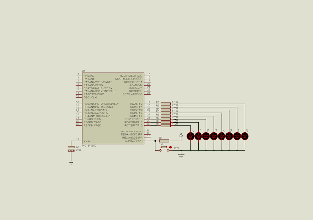
I select my DIY PIC18F4550 board I made to work with this example. On this board PORTD connects to an 8-bit LED output.
CCS PICC compiler has a lot of library functions. For digital input output, we need to use a few functions.
  1. output_x(value) - Writes an 8-bit data to any port x ( eg, A, B, C, etc).
  2. set_tris_x(value) - Set the data direction of x port. The value of 0 means output direction, otherwise an input direction.
  3. delay_ms(time) - Creates a timing delay in milli seconds. Time is an unsigned 16-bit integer ( 0 to 65535) milli seconds.
To program in CCS PICC:
  • include the device header file
  • use 'fuses' directive to set the configuration bits
  • use 'delay' directive to set the clock of the CPU
  • write the main function and others.

CCS PICC Source Code From GitHub


Schematic Diagram

Start To Blink PIC18F4550 Using CCS PICC
Schematic Diagram

Click here to download this example in zip file.


Arduino rotates a small servo motor with buttons


A servo is a kind of motor built in a module. The module contains a DC motor and a feed back control circuit. The feed back circuit regulates the motor rotating position to a specific angle receives from its master MCU, for example and Arduino.

Arduino rotates a small servo motor with buttons
Picture of this example

Controlling the position needs a specific timing. Conventionally, the signal timing frequency is 50 Hz. For more information about the servo motor timing, see this post

Servo motors are available in many physical sizes and interfaces. Choosing a servo motor depends on the application. With Arduino, there are many libraries to interface with external hardware module, including the servo motor. The Servo.h is already available after the installing of Arduino IDE. Servo control pin can be any where within the digital I/O pin and it's selected by source code writing.

To use the servo library we must #include <Servo.h>. Additionally, we must create a servo object, for example,

Servo sg90;

Using a very simple servo motor like the SG90 requires a few methods.

  1. attach() - sg90.attach(pin) : where pin is any pin on the Arduino board in use.
  2. write() - sg90.write(angle): where angle is between 0 and 190 degree.

Other sophisticated  servo motors have an angle reading line. But we don't need it here, as a simple example.

Arduino rotates a small servo motor with buttons
SG90 servo from device's specification

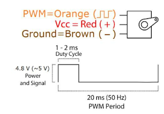
A typical servo SG90 has three lines - GND, VCC and Control. Control and VCC line requires a +5V pulse. Control line is the orange one's. It's no other than a PWM signal with low frequency.

Arduino rotates a small servo motor with buttons
SG90 pin diagram and its timing from the device's specification

In this example post, I use three tactile switches to rotate a SG90 servo motor with three corresponding angles 0 , 90 and 180 degrees respectively. I use four pin A0, A1, A2 and A3. 

Arduino rotates a small servo motor with buttons
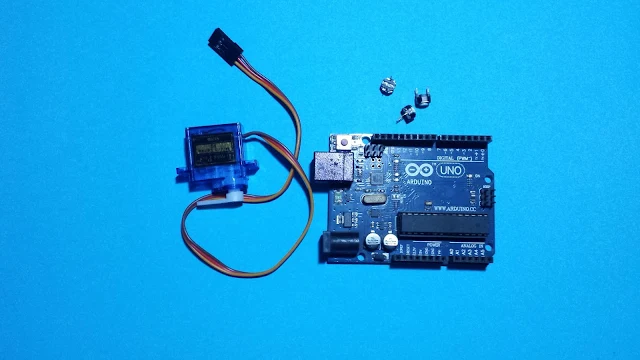
Some required parts

Arduino rotates a small servo motor with buttons
Connections Diagram

Arduino code from Github gist lists below.


Click here to download Arduino sketch.

Arduino rotates a servo motor using a potentiometer

In the previous post, I use three tactile switches to rotate a servo motor to three angle positions. However, using a potentiometer, we can continuously rotates the angle of servo motor in accordance to the adjustment of the potentiometer. 

Arduino rotates a servo motor using a potentiometer
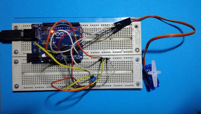
A picture of this example

With the  Arduino Servo.h and analogRead function, this task could be done easily. In this example, a potentiometer connects to pin A0 work as an analog input adjusting the angle of rotation. A servo again, connects to pin A3.

Arduino rotates a servo motor using a potentiometer
Connections Diagram

The analogRead() function return a 10-bit (1024) value from any reading from a specific analog input pin. Hence, this analog value must convert from 1024 to 180 in degree. This could be done by a simple equation as will be shown in source code.

Click here to download the sketch archive of this example.

Monday, February 15, 2021

PIC18F4550 Basic ADC Programming In CCS PICC

Introduction To ADC Module Of PIC18F4550


PIC18F4550 has a 10-bit ADC module. There are 13 analog input channels within PORTA and PORTB.


These analog input pins are multiplexed with digital input pins. By default, they are analog input pins.


Voltage Reference

There two analog voltage reference pins - VREF+ (RA3) and VREF-(RA2). these two pins are optional. 


They could be wired to external voltage reference source, or internally wired to VDD and GND, by software default setting. However, the total reference voltage must not exceed 5 V DC in magnitude.


Clock Source

Clock source fed to the ADC module come from its internal ADC RC oscillator, or the MCU clock source with programmable prescaler, up to 1:64.


Interfacing And Programming


Unlike writing a program in a low level language like assembly language, using a high level C programming language could make it done in a short time. CCS PICC provide a lot of peripherals libraries for those PICMicro devices including the PIC18F4550.


Those programmings in assembly need to know about the technical details of the module, especially the registers setting the make the peripheral to operate properly. However in a high level C for embedded controllers, those technical details were summarized in a few C syntax of its function library.


CCS PICC ADC Functional Overview

All functions list below make a configuration and the operation of the ADC module.

  1. setup_adc(mode) - select adc mode like on/off, adc clock etc.
  2. setup_adc_port(value) - set the number of available pins on the targeting device. The reference voltage pins could be include here.
  3. set_adc_channel(channel) - select the specific channel to convert.
  4. read_adc(mode) - start the conversion and return the result
  5. adc_done() - it's useful for testing the result. It return 0 if the conversion is completed.

By default the ADC result is 8-bit wide even the device's ADC is 10-bit. To use the device's full 10-bit resolution, use the #DEVICE ADC=10 after the device header file declaration.

Interfacing And Programming

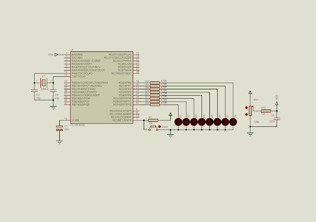
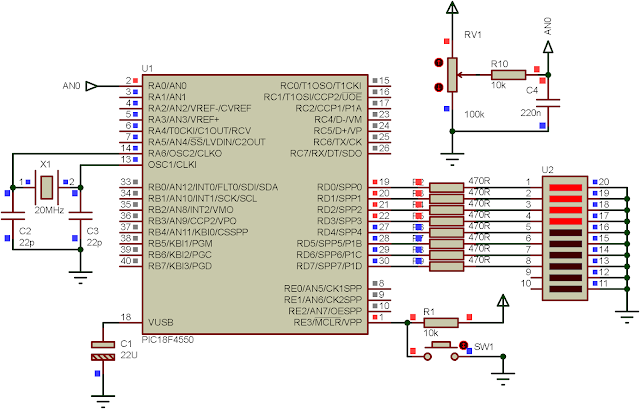
AN0 is the ADC channel 0 locates at RA0 of PORTA. This analog input channel read an analog input voltage value up to +5 V DC. The result is by default 8-bit. This 8-bit result display at the 8-bit PORTD output.
I configure the ADC clock to fed from its internal RC oscillator. Voltage reference for the ADC is internally wired to VDD and GND. MCU supplies at + 5 V DC. An external crystal is a 20 MHz crystal oscillator. 

PIC18F4550 Basic ADC Programming In CCS PICC
Schematic Diagram

Source stored in GitHub gist.

Click here to download archive of this example.

PIC18F4550 Basic ADC Programming In CCS PICC
A running program


LED Bar Graph Voltage Level Indicator With PIC18F4550

In the previous post, we show how to use ADC library function in CCS PICC. Here, the ADC is still in the discussion. In this example, I use almost the same source code, but one's difference is the output LED displays a bar graph pattern indicating the level of input voltage reading from the AN0.


ADC result is still 8-bit. This 8-bit result is scaled into an 9 number values correspond to 8 output LEDs on PORTD.


LED Bar Graph Voltage Level Indicator With PIC18F4550
LED bar graph running

Source code from GitHub gist.


Click here to download this example in zip file.

Schematic Diagram


Friday, February 12, 2021

ATMega32 Timer/Counter1 in Fast PWM Mode

Introduction

Timer/Counter1 module of ATMega32 is configurable to operate in fast Pulse Width Modulation (PWM) mode. There are two PWM blocks inside this module - PWM A and PWM B. Hence there are two corresponding output pins for these two blocks - OC1A and OC1B.

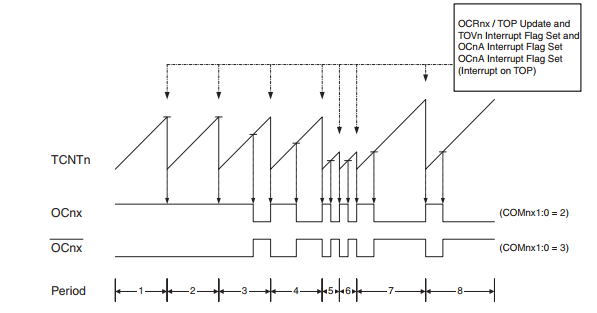
PWM output pulse has two mode, non-inverting and inverting mode. Its set and clear output pulse is the comparison between TCNT1 and OC1X register (OC1A or OC1B).

ATMega32 Timer/Counter1 in Fast PWM Mode
Fast PWM Mode - Timing Diagram

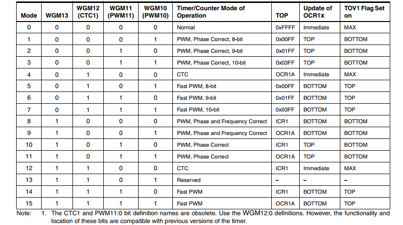
To make ATMega32 operates in this mode, user must set WGM13:0 of  Timer/Counter1 Control Register (TCCR1x) to 5, 6, 7, 14, or 15. Its frequency is calculated as below.

ATMega32 Timer/Counter1 in Fast PWM Mode
Fast PWM Mode Frequency

Its resolution is between 8 and 10-bit. Where,

ATMega32 Timer/Counter1 in Fast PWM Mode
Fast PWM Resolution

Programming

We need to configure some registers for fast PWM mode.
  • Timer/Counter1 Control Register A (TCCR1A)
ATMega32 Timer/Counter1 in Fast PWM Mode
TCCR1A

This register contains some settings for fast PWM mode. Compare Output Mode bits used for selecting between inverting and non-inverting mode of fast PWM mode.

ATMega32 Timer/Counter1 in Fast PWM Mode
Compare Output Mode Bits of TCCR1A

Waveform Generation Mode Bits must be set to any value as listed to make this module operates in fast PWM mode.

ATMega32 Timer/Counter1 in Fast PWM Mode
Waveform Generation Mode Bits

  • Timer/Counter1 Control Register B (TCCR1B)
This register contains prescaler selection for fast PWM mode. 
ATMega32 Timer/Counter1 in Fast PWM Mode
TCCR1B

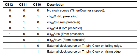
Clock Select Bits (CS12:10) allow user to set its prescaler effecting output frequency of fast PWM.

Timer/Counter1 Control Register B (TCCR1B)
Clock Selection Bits
  • Output Compare Register A 
This is a pair of 8-bit registers - OCR1AH and OCR1AL. This register is a compare variable of TCNT1 that toggle output waveform of PWM signal.
ATMega32 Timer/Counter1 in Fast PWM Mode
Output Compare Register A
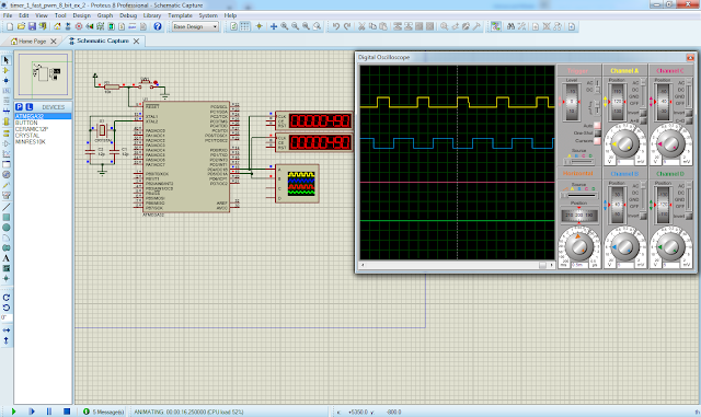
Now we make a simple example of using fast PWM. PWM A generates its output waveform on OC1A pin with a frequency of 490Hz, and 50% duty cycle. Output signal is non-inverting mode. Its resolution is 8-bit.

ATMega32 Timer/Counter1 in Fast PWM Mode
Schematic Diagram

Microcontroller clock is 16MHz from external crystal oscillator.

Source Code:

/*
 * timer_1_fast_pwm_8_bit_1.c
 *
 * Created: 2/10/2021 3:41:04 PM
 * Author : admin
 */ 

#include <avr/io.h>

int main(void)
{
/*OC1A PD5 Output*/
DDRD|=(1<<5);
/*Non-inverting mode, fast PWM 8-bit*/
TCCR1A=(1<<COM1A1)|(1<<COM1B1)|(1<<WGM12)|(1<<WGM10);
/*1:64 Prescaler*/
TCCR1B=(1<<CS11)|(1<<CS10);
/*Select 50% duty cycle*/
OCR1AH=0;
OCR1AL=127;
    while (1) 
    {
    }
}

Click here to download archive. 

Now let use both of this PWM output of Timer/Counter1 module. Either OC1A and OC1B output signal are inverting with different duty cycle, but its frequency is unique. 

ATMega32 Timer/Counter1 in Fast PWM Mode
Simulation screen shot

Source code:

/*
 * timer_1_fast_pwm_8_bit_2.c
 *
 * Created: 3/3/2021 8:38:00 PM
 * Author : admin
 */ 

#include <avr/io.h>


int main(void)
{
    /*OC1A and OC1B Output*/
DDRD=(1<<5)|(1<<4);
/*inverting fast PWM 8-bit*/
TCCR1A=(1<<COM1A1)|(1<<COM1B1)|(1<<COM1A0)|(1<<WGM12)|(1<<WGM10);
/*1::64 Pre-Scaler*/
TCCR1B=(1<<CS11)|(1<<CS10);
/*OC1A duty cycle*/
OCR1AH=0;
OCR1AL=127;
/*OC1B duty cycle*/
OCR1BH=0;
OCR1BL=75;
    while (1) 
    {
    }
}

Click here to download this example.


Search This Blog

Labels

25AA010A (1) 8051 (7) 93AA46B (1) ADC (30) Analog Comparator (1) Arduino (15) ARM (6) AT89C52 (7) ATMega32 (54) AVR (57) CCS PICC (28) DAC (1) DHT11 (2) Display (105) Distance Sensor (3) DS18B20 (3) dsPIC (2) dsPIC30F1010 (2) EEPROM (5) Environment Sensor (4) esp8266 (1) I2C (29) Input/Output (67) Interrupt (19) Keil (5) Keypad (10) LCD (46) Master/Slave (1) MAX7221 (1) MCP23017 (5) MCP23S17 (4) Meter (3) MikroC (2) Motor (15) MPLABX (66) Nokia 5110 LCD (3) OLED (2) One-Wire (6) Oscillator (8) PCB (6) PCD8544 (3) PCF8574 (5) PIC (107) PIC12F (2) PIC16F628A (2) PIC16F630 (1) PIC16F716 (3) PIC16F818 (10) PIC16F818/819 (2) PIC16F84A (15) PIC16F876A (1) PIC16F877A (9) PIC16F88 (1) PIC16F887 (60) PIC18 (19) PIC18F1220 (4) PIC18F2550 (3) PIC18F4550 (12) PWM (11) RTC (8) Sensor (10) SH1106 (1) Shift Register (11) Shift Registers (2) SPI (24) STM32 (6) STM32 Blue Pill (6) STM32CubeIDE (6) STM32F103C8T6 (6) SysTick (3) temperature sensor (11) Thermometer (21) Timer/Counter (30) TM1637 (2) UART (7) Ultrasonic (4) Voltmeter (7) WDT (1) XC16 (2) XC8 (94)