Introduction To ADC Module Of PIC18F4550
PIC18F4550 has a 10-bit ADC module. There are 13 analog input channels within PORTA and PORTB.
These analog input pins are multiplexed with digital input pins. By default, they are analog input pins.
Voltage Reference
There two analog voltage reference pins - VREF+ (RA3) and VREF-(RA2). these two pins are optional.
They could be wired to external voltage reference source, or internally wired to VDD and GND, by software default setting. However, the total reference voltage must not exceed 5 V DC in magnitude.
Clock Source
Clock source fed to the ADC module come from its internal ADC RC oscillator, or the MCU clock source with programmable prescaler, up to 1:64.
Interfacing And Programming
Unlike writing a program in a low level language like assembly language, using a high level C programming language could make it done in a short time. CCS PICC provide a lot of peripherals libraries for those PICMicro devices including the PIC18F4550.
Those programmings in assembly need to know about the technical details of the module, especially the registers setting the make the peripheral to operate properly. However in a high level C for embedded controllers, those technical details were summarized in a few C syntax of its function library.
CCS PICC ADC Functional Overview
All functions list below make a configuration and the operation of the ADC module.
- setup_adc(mode) - select adc mode like on/off, adc clock etc.
- setup_adc_port(value) - set the number of available pins on the targeting device. The reference voltage pins could be include here.
- set_adc_channel(channel) - select the specific channel to convert.
- read_adc(mode) - start the conversion and return the result
- adc_done() - it's useful for testing the result. It return 0 if the conversion is completed.
By default the ADC result is 8-bit wide even the device's ADC is 10-bit. To use the device's full 10-bit resolution, use the #DEVICE ADC=10 after the device header file declaration.
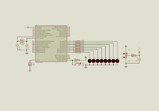
Interfacing And Programming
 |
| Schematic Diagram |
Source stored in GitHub gist.
 |
| A running program |
No comments:
Post a Comment