Monday, October 16, 2023

PIC16F84A Software UART Programming Example Using XC8

Overview

For a small embedded controller, UART(Universal Asynchronous Receiver-Transmitter) is a communication module inside the controller that send and receive serial data to or from its peripheral device. Its data format and speed are configurable.


PIC16F84A Software UART Progamming Example Using XC8
A Conventional UART Module

This communication module is commonly come with many popular micro-controller such as, AT89S52, ATMega32, or PIC16F877A, etc.


PIC16F84A Software UART Progamming Example Using XC8
A Simple Connection Between Two Devices
Each devices have their own supply voltage and clock generator. The connection requires only Tx/Rx pair and a common ground (GND). In some case it requires only a Tx either an Rx and a common ground signal.

Connecting device may use one of there three communication modes:

  1. simplex
  2. full duplex
  3. haft duplex

A UART frame consists of 5 elements:

  • Idle (logic high)
  • Start bit (logic low)
  • Data bits
  • Parity bit
  • Stop bit (logic high)

In most common settings of 8 data bits, on parity and 1 stop bit (aka 8N1).

PIC16F84A Software UART Progamming Example Using XC8
UART Signal

Signal could be transmitter or receiver signal. BCLK is a clock source inside each devices.

Baud or bits per second (bit/s) is the number of bits that processed per unit of time. Each data bits duration could be calculated a:

Ts = 1 / fs

 Where,

  • Ts : symbol duration
  • fs  : Baud or pits per second

For example, we select a 9600 baud. Hence, 

Ts = 1 / 9600 = 0.000104 second = 104 microseconds.

So each data bits (1's or 0's) must be around 104 microseconds.

For any controller that come with UART module, the programmer can set its baud by hardware setting and calculation.

However some controller doesn't have UART module inside (e.g PIC16F84A). So we can emulate UART by bit banging GPIO pins in software (Assembly or C language).

PIC16F84A UART Bit Banging 

Bit banging of serial communication could be done easily using software routine in most of programming languages. It requires additional program space. The programmer can select any microcontroller digital I/O pin to transmit or receiving data bits. Data processing takes a little period to send and receive serial data. However data errors may occur in some situation.

Some C compiler such as MikroC, CCS PICC have a software driver for bit banging. But we write our own function to process this task.

In this example, I select a 9600 baud, no parity and one stop bit (8N1). Start bit triggers from a high to low transition. Logic low signal should be delayed for around 100 microseconds. Each data bits should be sampled at the middle of data bits duration. The program samples receiving data bits around 60 microseconds. 

PIC16F84A Software UART Progamming Example Using XC8
Sample Data Bits For A 9600 Baud
The sample time begin after the middle of each data bits.

The program listens to serial data start of transmission. Whenever the high to low transition start the serial data reception will process.
PIC16F84A Software UART Progamming Example Using XC8
Received ASCII Data Showed On Port B
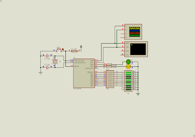
Whenever serial data received the controller will echo it to serial terminal. Serial terminal settings is 8N1(8-bit No Parity One Stop Bit). Serial data is in ASCII format. This ASCII character will show on Port B. Whenever a 0 ASCII character received it will toggle RA2. A 1 ASCII character will toggle RA3.

  1.  
  2. /*
  3.  for 9600 baud rate
  4.  * 1/9600 = 104uS per bit
  5.  * we can use 102.5uS per bit
  6.  */
  7.  
  8. #include <xc.h>
  9.  
  10. // PIC16F84A Configuration Bit Settings
  11.  
  12. // CONFIG
  13. #pragma config FOSC = XT // Oscillator Selection bits (XT oscillator)
  14. #pragma config WDTE = OFF // Watchdog Timer (WDT disabled)
  15. #pragma config PWRTE = OFF // Power-up Timer Enable bit (Power-up Timer is disabled)
  16. #pragma config CP = OFF // Code Protection bit (Code protection disabled)
  17.  
  18. #define _XTAL_FREQ 4000000
  19. #define TX RA0
  20. #define RX RA1
  21.  
  22. void sendChar(char data){
  23. TX=0;
  24. __delay_us(100);
  25. for(int i=0;i<8;i++){
  26. TX=data&(1<<0);
  27. data>>=1;
  28. __delay_us(75);
  29. }
  30. TX=1;
  31. __delay_us(100);
  32. }
  33.  
  34. char myChar=0,temp=0;
  35. void receiveChar(void){
  36. if(RX==0){
  37. __delay_us(100);
  38.  
  39. for(char i=0;i<8;i++){
  40. __delay_us(60);
  41. if(RX==1) myChar|=(1<<i);
  42. else myChar&=~(1<<i);
  43. }
  44. __delay_us(50);
  45. }
  46. }
  47. void sendText(char *text){
  48. while(*text) sendChar(*text++);
  49. }
  50.  
  51. void softUARTInit(void){
  52. PORTA=0x00;
  53. TRISA=0x02;
  54. PORTB=0;
  55. TRISB=0;
  56. TX=1;
  57. }
  58.  
  59. void main(){
  60.  
  61. softUARTInit();
  62. sendText("HELLO WORLD!\r\n");
  63. while(1){
  64. receiveChar();
  65. if(myChar!=0){
  66. PORTB=myChar;
  67. sendChar(myChar);
  68. //sendText("\r\n");
  69. if(myChar=='0') { RA2^=1; sendText(" Toggle RA2.\r\n");}
  70. if(myChar=='1') { RA3^=1; sendText(" Toggle RA3.\r\n");}
  71. myChar=0;
  72. }
  73. }
  74. }
  75.  

Click here to download this example.

PIC16F84A UART Bit Banging And Character LCD Example

A character LCD is very easy to control using a small micro-controller. Now I will send ASCII characters over UART terminal to the micro-controller. Those character will show on a 20x4 character LCD. 
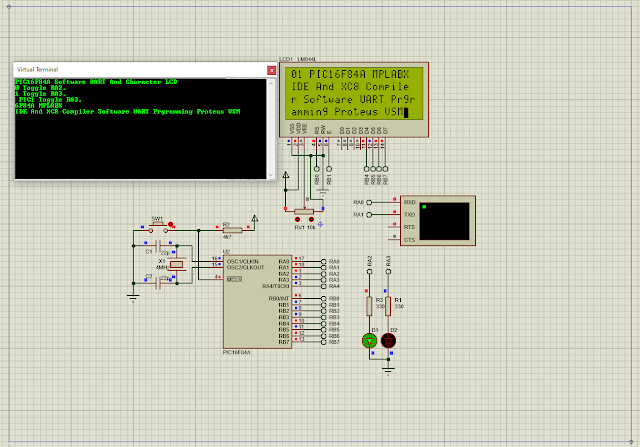
PIC16F84A Software UART Progamming Example Using XC8
Program Simulation

This example program consume half of program memory.

  1. /*
  2.  Software UART LCD Example 1
  3.  */
  4. #include <xc.h>
  5. #include "LCD4Bits.h"
  6.  
  7. // PIC16F84A Configuration Bit Settings
  8.  
  9. // CONFIG
  10. #pragma config FOSC = XT // Oscillator Selection bits (XT oscillator)
  11. #pragma config WDTE = OFF // Watchdog Timer (WDT disabled)
  12. #pragma config PWRTE = OFF // Power-up Timer Enable bit (Power-up Timer is disabled)
  13. #pragma config CP = OFF // Code Protection bit (Code protection disabled)
  14.  
  15. #define _XTAL_FREQ 4000000
  16. #define TX RA0
  17. #define RX RA1
  18.  
  19. void sendChar(char data){
  20. TX=0;
  21. __delay_us(100);
  22. for(int i=0;i<8;i++){
  23. TX=data&(1<<0);
  24. data>>=1;
  25. __delay_us(75);
  26. }
  27. TX=1;
  28. __delay_us(100);
  29. }
  30.  
  31. char myChar=0,temp=0;
  32. void receiveChar(void){
  33. if(RX==0){
  34. __delay_us(100);
  35. for(char i=0;i<8;i++){
  36. __delay_us(60);
  37. if(RX==1) myChar|=(1<<i);
  38. else myChar&=~(1<<i);
  39. }
  40. __delay_us(100);
  41. }
  42. }
  43. void sendText(char *text){
  44. while(*text) sendChar(*text++);
  45. }
  46.  
  47. void softUARTInit(void){
  48. PORTA=0x00;
  49. TRISA=0x02;
  50. PORTB=0;
  51. TRISB=0;
  52. TX=1;
  53. }
  54.  
  55. void main(){
  56. uint8_t line=1,charNum=1;
  57. softUARTInit();
  58. lcdInit();
  59. sendText("PIC16F84A Software UART And Character LCD\r\n");
  60. lcdString("PIC16F84A 20x4 LCD");
  61. lcdXY(1,2);
  62. lcdString("Software Delay UART");
  63. lcdXY(1,3);
  64. lcdString("Programming Example");
  65. lcdXY(1,4);
  66. lcdString("MPLABX IDE And XC8");
  67. __delay_ms(2000);
  68. lcdClear();
  69.  
  70. while(1){
  71. receiveChar();
  72. if(myChar!=0&&myChar!=0x08){
  73. sendChar(myChar);
  74. if(myChar=='0') { RA2^=1; sendText(" Toggle RA2.\r\n");}
  75. if(myChar=='1') { RA3^=1; sendText(" Toggle RA3.\r\n");}
  76. if(myChar==0x0D) {
  77. line+=1;
  78. lcdXY(1,line);
  79. charNum=1;
  80. }else{
  81. lcdData(myChar);
  82. }
  83. charNum+=1;
  84. if(charNum>20) {charNum=1; line+=1; lcdXY(charNum,line);}
  85. if(line>4){line=1;lcdXY(charNum,line);}
  86. myChar=0;
  87. }
  88. }
  89. }

Click here to download its source file.


Wednesday, October 11, 2023

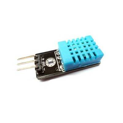
PIC16F84A DHT11 Temperature And Humidity Sensor And Character LCD Interfacing Using XC8

Overview

The DHT11 temperature and humidity sensor features a temperature and humidity sensor
complex with a calibrated digital signal output. By using the exclusive digital-signal-acquisition
technique and temperature and humidity sensing technology, it ensures high reliability and
excellent long-term stability. This sensor includes a resistive-type humidity measurement
component and an NTC temperature measurement component, and connects to a high performance 8-bit micro-controller, offering excellent quality, fast response, anti-interference
ability and cost-effectiveness.

PIC16F84A DHT11 Temperature And Humidity Sensor And Character LCD Interfacing Using XC8
DHT11 Humidity & Temperature
Sensor


Parameters

Relative Humidity
Resolution:             16Bit
Repeatability:         ±1%RH
Accuracy:               25℃ ±5%RH
Interchangeability:  Fully interchangeable
Response time:       1/e (63%)25℃ 6s
                                1m/s Air 6s
Hysteresis:             <±0.3%RH
Long-term stability: <±0.5%RH/yr


Temperature
Resolution:             16Bit
Repeatability:         ±1℃
Accuracy:               25℃ ±2℃
Response time:       1/e (63%) 10S


Electrical Characteristics
Power supply:         DC 3.3~ 5.5V
Supply current:       Measure 0.3mA Standby 60μA
Sampling period:     Secondary Greater than 2 seconds 

Micro-controller Interfacing

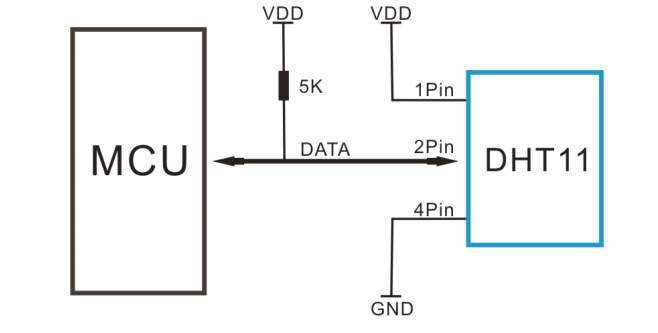
This sensor uses only one bidirectional pin to accept a start signal from the micro-controller. It will send back its serial data with 40 bits length to the micro-controller. 

PIC16F84A DHT11 Temperature And Humidity Sensor And Character LCD Interfacing Using XC8
Typical Application
A 5 kill Ohms pull up resistor is usable for a connection length below 20 meters. For the connection over 20 meters, choose a suitable value of pull up resistor. Its power supply is between 3 to 5.5V DC. For a stable operation at long range, use a an appropriate filtering capacitor.

Bi-directional Serial Communication

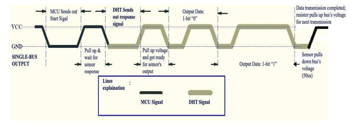
The micro-controller output pin is in normal high logic standby mode. It must issue a start command by putting its data pin to low level around 18 milliseconds, and then the data pin must be pull up to high logic for 30 microseconds. DHT11 will send a low to high logic respond signal to micro-controller.

PIC16F84A DHT11 Temperature And Humidity Sensor And Character LCD Interfacing Using XC8
Overall Communication Process

Micro-controller's data pin must be assigned to input direction to accept serial data from DHT11 sensor.

MCU sends out start signal and DHT11 responses
The response signal from DHT11 is a low (around 80 microseconds) to high logic level (around 80 microseconds).

After this response signal, the sensor will send its serial data with 40 bits length. A low logic level of 50 microseconds indicates a start of each data bits. After that is a high logic level with two distinct duration that identify between 0's and 1's logic value of each data bits.

PIC16F84A DHT11 Temperature And Humidity Sensor And Character LCD Interfacing Using XC8
Data"0" Indication
Logic high with a duration around 25 to 28 microseconds indicates a 0's data bit.
 
PIC16F84A DHT11 Temperature And Humidity Sensor And Character LCD Interfacing Using XC8
Data "1" Indication

Logic high with a duration around microseconds indicates a 1's data bit.

PIC16F84A DHT11 Temperature And Humidity Sensor And Character LCD Interfacing Using XC8
logic 0's and 1's values

To sample this signal, the micro-controller should use a timer or a simple delay function to detect the duration of high logic signal.

PIC16F84A DHT11 Temperature And Humidity Sensor And Character LCD Interfacing Using XC8
Data Timing Diagram

After the transmission of its 40 bits data, a low end time with a duration of 50 microseconds indicate the end of transmission. It will turn to logic high due to a pull up resistor.

Data Format 

Its total data is 40 bits wide that include these data bytes,

  1. byte 0 - decimal humidity value
  2. byte 1 - empty humidity value
  3. byte 2 - decimal temperature value
  4. byte 4 - empty temperature value
  5. byte 5 - parity.

This sensor has only decimal humidity and temperature value. Its empty value data bytes are ignore.

It parity byte is useful for error checking. We can calculate as follow,

parity(byte 5) = byte 0 + byte 1 + byte 2 + byte 3

If this calculation is not verified then the micro-controller must read this sensor data again. For example, the sensor is read 53RH (humidity) and 24 degree Celsius (temperature) with a parity of 77 (in binary 0100 1101). We can calculate it as below,

PIC16F84A DHT11 Temperature And Humidity Sensor And Character LCD Interfacing Using XC8
Parity Check
That is,

0011 0101 + 0000 0000 + 0001 1000 + 0000 0000 = 0100 1101

This 40-bit data is correct. So we can use it.

Micro-controller Interfacing And Programming

A simple 8-bit micro-controller could command and decode the serial data from this sensor easily. A 8051 micro-controller could interface with this sensor with a simple display output. The firmware require a little space of micro-controller program memory space.

PIC16F84A DHT11 Temperature And Humidity Sensor And Character LCD Interfacing Using XC8
Program Simulation

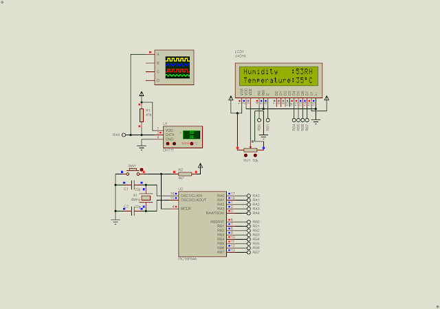
A simple 8-bit PIC micro-controller is suitable for this task, due to a little amount of I/O, small footprint, and a reasonable amount of RAM and ROM space. I use a PIC16F84A micro-controller. This controller has only digital I/O, without analog I/O and communication module. We don't need these peripheral here. I use Proteus VSM to simulate this sample program because this micro-controller was burn out a long time ago. I will not buy it more. Currently there are a lot of newly designed controllers from Microchip Technology with rich peripherals and low cost.

PIC16F84A DHT11 Temperature And Humidity Sensor And Character LCD Interfacing Using XC8
Sample Serial Data

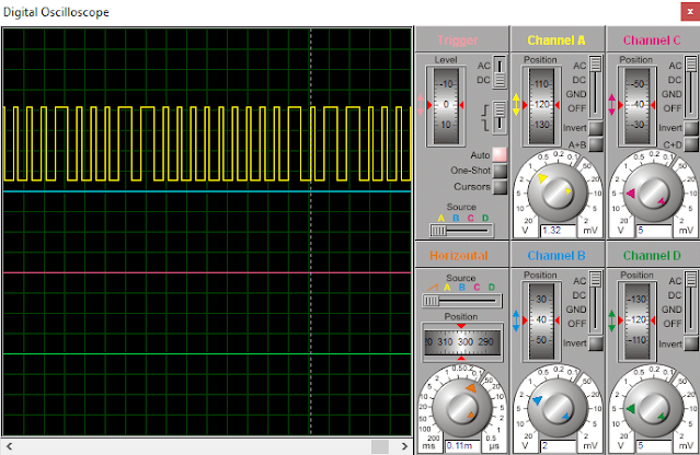
We can see its serial data transmission over the virtual DSO screen of the simulator. To check this serial signal without a micro-controller we can use a switch instead with an oscilloscope. We just press the switch to make low signal and the release it. The output serial data of this sensor will be sent out.

  1. /*
  2.  * PIC16F84A DHT11 Temperature and Humidity Sensor Interfacing
  3.  * With HD44780 Character LCD
  4.  * MPLABX IDE v1.51
  5.  * XC8 v2.36
  6.  */
  7.  
  8. #include <xc.h>
  9. #include "LCD4Bits.h"
  10.  
  11. #define _XTAL_FREQ 4000000UL
  12. #define DATA_PIN RA4
  13. #define DATA_DIR TRISA4
  14.  
  15. uint8_t data[5];
  16. void readDHT11(void){
  17. for(uint8_t i=0;i<5;i++) data[i]=0;
  18. DATA_DIR=0;
  19. DATA_PIN=1;
  20. __delay_ms(10);
  21. DATA_PIN=0;
  22. __delay_ms(18);
  23. DATA_PIN=1;
  24. __delay_us(30);
  25. DATA_PIN=0;
  26. DATA_DIR=1;
  27. __delay_us(10);
  28. while(DATA_PIN==0);
  29. __delay_us(10);
  30. while(DATA_PIN==1);
  31. __delay_us(10);
  32.  
  33. //Start of Transmission
  34. for(uint8_t i=0;i<5;i++) {
  35. for(uint8_t j=0;j<8;j++){
  36. __delay_us(5);
  37. while(DATA_PIN==0);
  38. __delay_us(50);
  39. if(DATA_PIN==1) { data[i]|=(1<<7-j);}
  40. }
  41. __delay_us(10);
  42. }
  43. /*CRC Calculation - the last byte data[4] is check sum*/
  44. uint8_t crc = data[0]+data[1]+data[2]+data[3];
  45. if(crc!=data[4]) {for(uint8_t i=0;i<4;i++) data[i]=0; return;}
  46. __delay_us(10);
  47. }
  48. int main(void){
  49. PORTA=0;
  50. TRISA=0;
  51.  
  52. PORTB=0;
  53. TRISB=0;
  54.  
  55. lcdInit();
  56.  
  57. lcdXY(1,1); lcdString("Humidity : ");
  58. lcdXY(1,2); lcdString("Temperature: ");
  59.  
  60. while(1){
  61. readDHT11();
  62.  
  63. lcdXY(13,1);
  64. /*Humidity is below 90RH*/
  65. if(data[0]>=10) lcdData(48+(data[0]%100)/10);
  66. lcdData(48+(data[0]%10));
  67. lcdData('R');
  68. lcdData('H');
  69.  
  70. /*Temperature is below 50 degree Celsius*/
  71. lcdXY(13,2);
  72. if(data[2]>=10) lcdData(48+data[2]/10);
  73. lcdData(48+(data[2]%10));
  74. lcdData(223);
  75. lcdData('C');
  76. __delay_ms(500);
  77. }
  78. return 0;
  79. }

Built program uses only 50% of program memory. We can add a few switches and an output relay or transistor to set the a temperature condition with an output device (an AC or DC fan).

PIC16F84A DHT11 Temperature And Humidity Sensor And Character LCD Interfacing Using XC8
MPLABX IDE Build Output
The MPLABX IDE release is v1.51 (2012). I use the XC8 v2.36. It's a free version without code optimization and technical support. Click here to download its source file.


Search This Blog

Labels

25AA010A (1) 8051 (7) 93AA46B (1) ADC (30) Analog Comparator (1) Arduino (15) ARM (6) AT89C52 (7) ATMega32 (54) AVR (57) CCS PICC (28) DAC (1) DHT11 (2) Display (105) Distance Sensor (3) DS18B20 (3) dsPIC (2) dsPIC30F1010 (2) EEPROM (5) Environment Sensor (4) esp8266 (1) I2C (29) Input/Output (67) Interrupt (19) Keil (5) Keypad (10) LCD (46) Master/Slave (1) MAX7221 (1) MCP23017 (5) MCP23S17 (4) Meter (3) MikroC (2) Motor (15) MPLABX (66) Nokia 5110 LCD (3) OLED (2) One-Wire (6) Oscillator (8) PCB (6) PCD8544 (3) PCF8574 (5) PIC (107) PIC12F (2) PIC16F628A (2) PIC16F630 (1) PIC16F716 (3) PIC16F818 (10) PIC16F818/819 (2) PIC16F84A (15) PIC16F876A (1) PIC16F877A (9) PIC16F88 (1) PIC16F887 (60) PIC18 (19) PIC18F1220 (4) PIC18F2550 (3) PIC18F4550 (12) PWM (11) RTC (8) Sensor (10) SH1106 (1) Shift Register (11) Shift Registers (2) SPI (24) STM32 (6) STM32 Blue Pill (6) STM32CubeIDE (6) STM32F103C8T6 (6) SysTick (3) temperature sensor (11) Thermometer (21) Timer/Counter (30) TM1637 (2) UART (7) Ultrasonic (4) Voltmeter (7) WDT (1) XC16 (2) XC8 (94)