Overview
For a small embedded controller, UART(Universal Asynchronous Receiver-Transmitter) is a communication module inside the controller that send and receive serial data to or from its peripheral device. Its data format and speed are configurable.
 |
| A Conventional UART Module |
This communication module is commonly come with many popular micro-controller such as, AT89S52, ATMega32, or PIC16F877A, etc.
 |
| A Simple Connection Between Two Devices |
Connecting device may use one of there three communication modes:
- simplex
- full duplex
- haft duplex
A UART frame consists of 5 elements:
- Idle (logic high)
- Start bit (logic low)
- Data bits
- Parity bit
- Stop bit (logic high)
In most common settings of 8 data bits, on parity and 1 stop bit (aka 8N1).
 |
| UART Signal |
Signal could be transmitter or receiver signal. BCLK is a clock source inside each devices.
Baud or bits per second (bit/s) is the number of bits that processed per unit of time. Each data bits duration could be calculated a:
Where,
- Ts : symbol duration
- fs : Baud or pits per second
For example, we select a 9600 baud. Hence,
Ts = 1 / 9600 = 0.000104 second = 104 microseconds.
So each data bits (1's or 0's) must be around 104 microseconds.
For any controller that come with UART module, the programmer can set its baud by hardware setting and calculation.
However some controller doesn't have UART module inside (e.g PIC16F84A). So we can emulate UART by bit banging GPIO pins in software (Assembly or C language).
PIC16F84A UART Bit Banging
Bit banging of serial communication could be done easily using software routine in most of programming languages. It requires additional program space. The programmer can select any microcontroller digital I/O pin to transmit or receiving data bits. Data processing takes a little period to send and receive serial data. However data errors may occur in some situation.
Some C compiler such as MikroC, CCS PICC have a software driver for bit banging. But we write our own function to process this task.
In this example, I select a 9600 baud, no parity and one stop bit (8N1). Start bit triggers from a high to low transition. Logic low signal should be delayed for around 100 microseconds. Each data bits should be sampled at the middle of data bits duration. The program samples receiving data bits around 60 microseconds.
 |
| Sample Data Bits For A 9600 Baud |
The program listens to serial data start of transmission. Whenever the high to low transition start the serial data reception will process.
 |
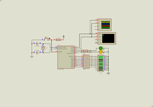
| Received ASCII Data Showed On Port B |
Click here to download this example.
PIC16F84A UART Bit Banging And Character LCD Example
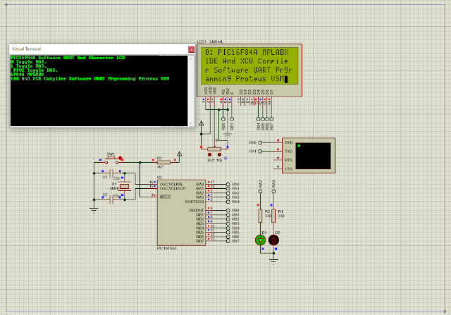
A character LCD is very easy to control using a small micro-controller. Now I will send ASCII characters over UART terminal to the micro-controller. Those character will show on a 20x4 character LCD.
 |
| Program Simulation |
This example program consume half of program memory.
Click here to download its source file.
No comments:
Post a Comment