728x90

Showing posts with label PIC16F84A. Show all posts

Friday, July 11, 2025

DIY PICMicro Low Pin Count DIP Prototype Board

Overview 

Using a prototype board for micro-controller firmware testing could save time and safer. Putting an on-board device programmer with prototype board could be more satisfy for electronic hobbyists.

I have some PIC18 and PIC16 series of micro-controllers left from previous projects. I don't know what to do with them anymore. So I put them on single board to PIC program testing next time I need them without checking their pin diagram, and wiring them on bread board. 

DIY PICMicro Low Pin Count DIP Prototype Board
PCB Front View

DIY PICMicro Low Pin Count DIP Prototype Board
PCB Back View
 

I designed a PCB with a 

  1. PICKit2 device programmer (with AVR ISP header)
  2. +5VDC and +3.3VDC low drop out power supply
  3.  RS-232 to TTL logic converter
  4. I2C DS1307 RTC and 24LC08 EEPROM 
  5. 4-bit LCD (HD4478)
  6. 3-digit 056'common cathode multiplexing display 
  7. One passive buzzer with transistor driver (using CCP1 PWM output pin of PIC16F876A)
  8. 8-LED that connects to PORTC of PIC16F876A
  9. A 4x4 keypad matrix that connects to PORTB of PIC16F876A
  10. Three analog inputs (one LM35 and two potentiometers) that connect to RA0...RA1 of PIC16F876A. 
  11. A 28-pin IC socket for 28-pin PIC devices
  12. A 20-pin IC socket for 20-pin PIC devices
  13. A 18-pin IC socket for 18-pin PIC devices
  14. A 14-pin IC socket for 14-pin PIC devices
  15. And a 8-pin IC socket for 8-pin PIC devices

This board seem to be a large PCB with two copper layer near a size of an A4 paper that I'm not yet fabricate it. It need a PCB fabrication service.

Schematic

I use Protues VSM Release 8.16 SP3 to design draw its circuit diagram. Some components are not in its original libraries. So I find and download some devices symbol, footprints and 3D objects from snapeda website. I separate its schematic into A4 sheets. 


DIY PICMicro Low Pin Count DIP Prototype Board
Sheet #1

DIY PICMicro Low Pin Count DIP Prototype Board
Sheet #2

DIY PICMicro Low Pin Count DIP Prototype Board
Sheet #3

DIY PICMicro Low Pin Count DIP Prototype Board
Sheet #4

DIY PICMicro Low Pin Count DIP Prototype Board
Sheet #5

This board could fit,

  1. 28-pin PIC microcontrollers: PIC16F876A, PIC16F886, etc.
  2. 20-pin PIC microcontrollers: PIC16F1459(USB), PIC16F690, etc.
  3. 18-pin PIC microcontrollers: PIC16F1827, PIC16F84A, PIC16F818, etc.
  4. 14-pin PIC microcontrollers: PIC16F630, PIC16F676, etc.
  5. 8-pin PIC microcontrollers: PIC12F629, PIC12F675, PIC12F683, etc.

These are some mid-range PIC micro-controllers I have at my own workshop.

Printed Circuit Board (PCB)

This board size is 8.02x6.30 inches that could be a little bit expensive to order from any professional PCB fabrication service. But if we need to use it with classmate or friend the share cost is cheaper.

DIY PICMicro Low Pin Count DIP Prototype Board
Top Copper non-mirror


DIY PICMicro Low Pin Count DIP Prototype Board
Bottom Copper


DIY PICMicro Low Pin Count DIP Prototype Board
Top Silk

I preview this PCB on an online Gerber viewer software.

DIY PICMicro Low Pin Count DIP Prototype Board
Gerber View Top Copper

DIY PICMicro Low Pin Count DIP Prototype Board
Gerber View Bottom Copper


 Click here to download its design file.


PCB Fabrication

I have been using PCBWay for many years now. PCBWay fabricate PCBs at low cost, fast processing time for only 24 hours, and fast delivery time using any carrier options. This double side 10cmx10cm can be fabricate at only 5USD for 5 to 10pcs by PCBWay. It's a standard PCB with silk screen and solder mask.

A DIY dsPIC30F2010 and dsPIC30F1010 Prototype Board with Programmer
10 PCBs for only 5USD
 

For different size of PCB we can instantly quote on PCBWay website using a zip PCB Gerber file without account.


A DIY dsPIC30F2010 and dsPIC30F1010 Prototype Board with Programmer
PCBWay Instant Quote
 

We can accurately see the preview of fabricated PCB generated by the company's online Gerber file viewer.

PCBWay also offer PCBA assembly service at reasonable price.

A DIY dsPIC30F2010 and dsPIC30F1010 Prototype Board with Programmer
PCBWay PCB Assembly Service


Friday, November 10, 2023

PIC16F84A Simple Frequency Meter With LCD Using XC8

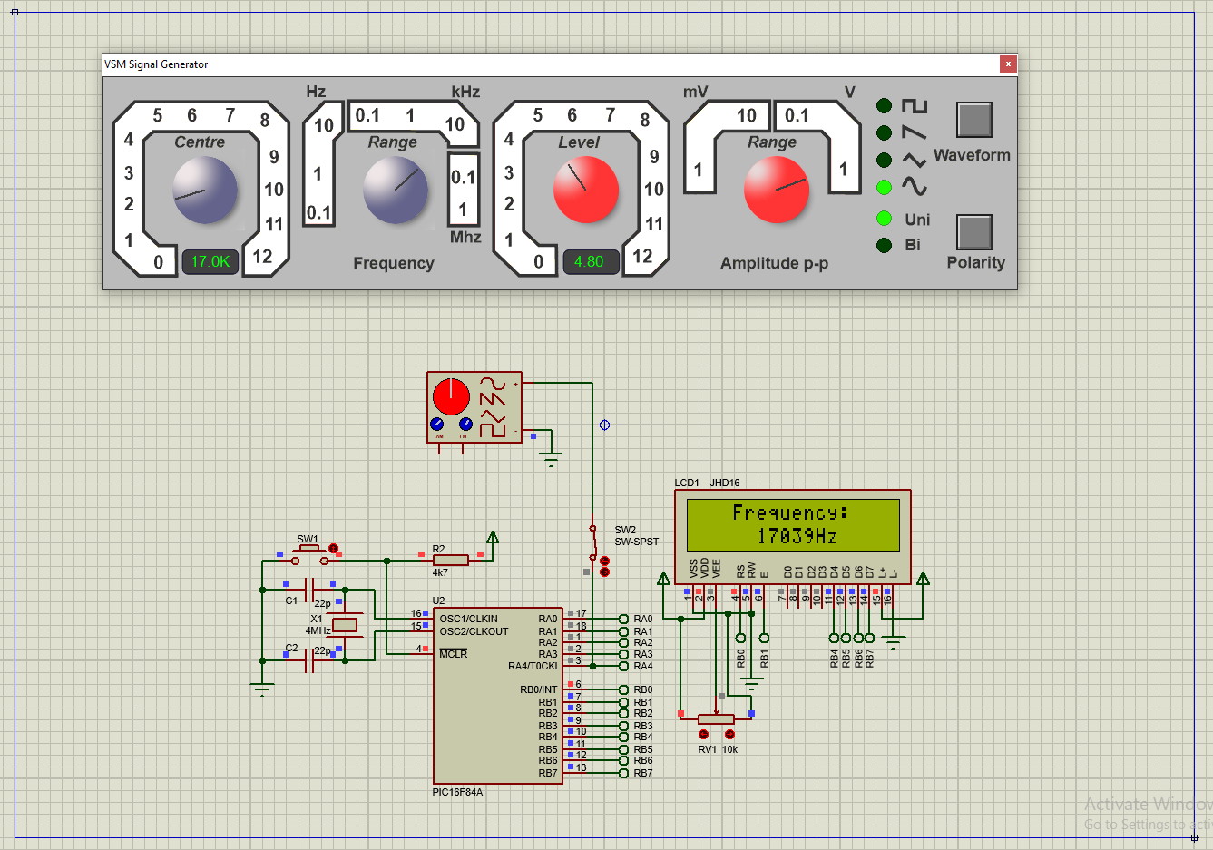
Frequency meter can be made using a conventional digital ICs with a big size, and complicated circuit connection. A small 8-bit micro-controller could do this job using a low level Assembly language or even a higher level C language.

In this example, I use an 8-bit PIC16F84A micro-controller to count external TTL input pulse. The total count will update for every seconds.

PIC16F84A Simple Frequency Meter With LCD Using XC8
Simulating Program


I use RA4/T0CKI (Timer0 External Clock Input) pin to count external TTL pulse. Since Timer0 is only 8-bit wide the maximum counting is only 255 counts. So I add Timer0 Interrupt to increase the maximum counts. I use XC8 built-in delay function to create a precise 1000 ms (1 second) delay before the summation of external pulse is evaluated. A 16x2 character LCD is suitable for this example.

  1. #include <stdio.h>
  2. #include <xc.h>
  3.  
  4. #define _XTAL_FREQ 4000000UL
  5.  
  6. #include "LCD4Bits.h"
  7.  
  8. void tmr0Init(void){
  9. PORTA=0;
  10. TRISA4=1;
  11. T0CS=1;
  12. T0SE=0;
  13. PSA=1;
  14. OPTION_REGbits.PS=0;
  15. T0IE=1;
  16. GIE=1;
  17. T0IF=0;
  18. }
  19.  
  20. long TMR0H=0;
  21.  
  22. void interrupt T0_ISR(void){
  23. if(T0IF){
  24. TMR0H+=1;
  25. T0IF=0;
  26. }
  27. }
  28.  
  29. int main(void){
  30. unsigned char freq[10];
  31. uint32_t temp=0;
  32. PORTB=0;
  33. TRISB=0;
  34. lcdInit();
  35. tmr0Init();
  36. lcdXY(4,1);
  37. lcdString("PIC16F84A");
  38. lcdXY(1,2);
  39. lcdString("Frequency Meter");
  40. __delay_ms(1000);
  41. lcdCommand(CLEAR_SCREEN);
  42. __delay_ms(5);
  43. lcdXY(4,1);
  44. lcdString("Frequency:");
  45. TMR0H=0;
  46. TMR0=0;
  47. while(1){
  48. __delay_ms(1000);
  49. temp=(TMR0H<<8)+TMR0;
  50. lcdXY(6,2);
  51. sprintf(freq,"%uHz ",temp);
  52. lcdString(freq);
  53. TMR0H=0;
  54. TMR0=0;
  55. }
  56. return 0;
  57. } 

I can not test it on bread-board because this chip was burn out. And I only have some newer PIC chips. So this program can only be tested using a simulator like Proteus. We can use another PIC chip like the PIC16F628A, and CCS PICC compiler

PIC16F84A Simple Frequency Meter With LCD Using XC8
Resource Usage


This program require 69.5% of program memory, and 89.7% of data memory. Click here to download this example.


Thursday, November 9, 2023

PIC16F84A EEPROM Reading And Writing Example Using XC8

PIC16F84A contains 68 bytes of EEPROM non-volatile memory. It's useful for storing some setting parameters when the MCU is powered off. EEPROM has a slower access time than SRAM and Flash memory. But it has a higher endurance compares to Flash memory. We can erase or write EEPROM up to 10 million times.

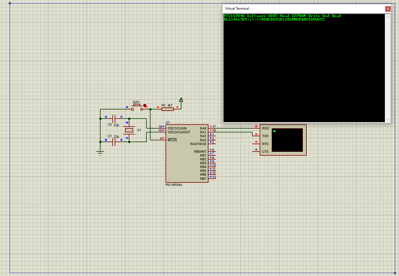
PIC16F84A EEPROM Reading And Writing Example Using XC8
Running Program


Using a low level Assembly language or C programming language without EEPROM library, we can access to this memory via these four SRFs,

  1. EEDATA - EEPROM Data Register
  2. EEADR   - EEPROM Address Register
  3. EECON1
  4. and EECON2.

EEPROM Control Regsiter 1 (EECON1) has some control bits to read, write, and status checking of EEPROM operations. 

PIC16F84A EEPROM Reading And Writing Example Using XC8
EECON1 Register


Using XC8 we can use all of these registers to read or write to EEPROM. However XC8 compiler has a built-in EEPROM library that's very easy to use. To read or write EEPROM, we only need these functions,

  1. EEPROM_READ(address)
  2. EEPROM_WRITE(address, data) .

We just include the "xc.h" header file to call these functions.

Example #1 : EEPROM Writing And Reading

In this example, the program write a set of ASCII characters to EEPROM starting from address 0. Then the controller read them back, and they will be shown on virtual terminal. I use software UART (bit banging) to process serial data.

  1.  
  2. /*
  3.  for 9600 baud rate
  4.  * 1/9600 = 104uS per bit
  5.  * we can use 102.5uS per bit or above
  6.  */
  7.  
  8. #include <xc.h>
  9.  
  10. // PIC16F84A Configuration Bit Settings
  11.  
  12. // CONFIG
  13. #pragma config FOSC = XT // Oscillator Selection bits (XT oscillator)
  14. #pragma config WDTE = OFF // Watchdog Timer (WDT disabled)
  15. #pragma config PWRTE = OFF // Power-up Timer Enable bit (Power-up Timer is disabled)
  16. #pragma config CP = OFF // Code Protection bit (Code protection disabled)
  17.  
  18. #define _XTAL_FREQ 4000000
  19. #define TX RA0
  20. #define RX RA1
  21.  
  22. void sendChar(char data){
  23. TX=0;
  24. __delay_us(100);
  25. for(int i=0;i<8;i++){
  26. TX=data&(1<<0);
  27. data>>=1;
  28. __delay_us(75);
  29. }
  30. TX=1;
  31. __delay_us(100);
  32. }
  33.  
  34. char myChar=0,temp=0;
  35. void receiveChar(void){
  36. if(RX==0){
  37. __delay_us(100);
  38.  
  39. for(char i=0;i<8;i++){
  40. __delay_us(60);
  41. if(RX==1) myChar|=(1<<i);
  42. else myChar&=~(1<<i);
  43. }
  44. __delay_us(100);
  45. }
  46. }
  47.  
  48. void sendText(char *text){
  49. while(*text) sendChar(*text++);
  50. }
  51.  
  52. void softUARTInit(void){
  53. PORTA=0x00;
  54. TRISA=0x02;
  55. PORTB=0;
  56. TRISB=0;
  57. TX=1;
  58. }
  59.  
  60. void main(){
  61.  
  62. softUARTInit();
  63. sendText("PIC16F84A Software UART Read EEPROM Write And Read\r\n");
  64. for(uint8_t i=0;i<43;i++) {EEPROM_WRITE(i,i+48);while(WR==1);}
  65. for(uint8_t i=0;i<43;i++) {sendChar(EEPROM_READ(i)); while(RD==1);}
  66. sendText("\r\n");
  67. while(1){
  68.  
  69. }
  70. }
  71.  

Click here to download this example.


Example #2: Initializing EEPROM Data

Without using the EEPROM_WRITE function, we can initialize the EEPROM space. We use the __EEPROM_DATA() macro. The input is an 8 parameters. Each parameters are the 1 byte EEPROM data. For example,

__EEPROM_DATA('H','E','L','L','O','S','I','R'); .

In this example, I initialize some ASCII characters on EEPROM space. Then the program read them back before they are sent over the software UART terminal.

  1. /*
  2.  for 9600 baud rate
  3.  * 1/9600 = 104uS per bit
  4.  * we can use 102.5uS per bit or above
  5.  */
  6.  
  7. #include <xc.h>
  8.  
  9. // PIC16F84A Configuration Bit Settings
  10.  
  11. // CONFIG
  12. #pragma config FOSC = XT // Oscillator Selection bits (XT oscillator)
  13. #pragma config WDTE = OFF // Watchdog Timer (WDT disabled)
  14. #pragma config PWRTE = OFF // Power-up Timer Enable bit (Power-up Timer is disabled)
  15. #pragma config CP = OFF // Code Protection bit (Code protection disabled)
  16.  
  17. #define _XTAL_FREQ 4000000
  18. #define TX RA0
  19. #define RX RA1
  20.  
  21. __EEPROM_DATA('H','E','L','L','O','S','I','R');
  22. __EEPROM_DATA('P','I','C','1','6','F','8','4');
  23. __EEPROM_DATA(' ','S','i','m','p','l','e',' ');
  24. __EEPROM_DATA('U','A','R','T',' ','P','r','o');
  25. __EEPROM_DATA('g','r','a','m','m','i','n','g');
  26. __EEPROM_DATA(' ','W','i','t','h',' ','M','P');
  27. __EEPROM_DATA('L','A','B','X',' ','I','D','E');
  28. __EEPROM_DATA(' ','X','C','8',' ','C',' ','.');
  29.  
  30. void sendChar(char data){
  31. TX=0;
  32. __delay_us(100);
  33. for(int i=0;i<8;i++){
  34. TX=data&(1<<0);
  35. data>>=1;
  36. __delay_us(75);
  37. }
  38. TX=1;
  39. __delay_us(100);
  40. }
  41.  
  42. char myChar=0,temp=0;
  43. void receiveChar(void){
  44. if(RX==0){
  45. __delay_us(100);
  46.  
  47. for(char i=0;i<8;i++){
  48. __delay_us(60);
  49. if(RX==1) myChar|=(1<<i);
  50. else myChar&=~(1<<i);
  51. }
  52. __delay_us(100);
  53. }
  54. }
  55. void sendText(char *text){
  56. while(*text) sendChar(*text++);
  57. }
  58.  
  59. void softUARTInit(void){
  60. PORTA=0x00;
  61. TRISA=0x02;
  62. PORTB=0;
  63. TRISB=0;
  64. TX=1;
  65. }
  66.  
  67. void main(){
  68.  
  69. softUARTInit();
  70. sendText("PIC16F84A Software UART Read EEPROM Example 1\r\n");
  71. for(uint8_t i=0;i<8;i++) sendChar(EEPROM_READ(i));
  72. sendText("\r\n");
  73. for(uint8_t i=8;i<64;i++) sendChar(EEPROM_READ(i));
  74. while(1){
  75.  
  76. }
  77. }
  78.  

Click here to download its source file.

Search This Blog

Labels

23K256 (1) 24C16B (2) 25AA010A (2) 8051 (7) 93AA46B (1) ADC (34) Analog Comparator (1) Arduino (16) ARM (13) AT89C52 (7) ATMega32 (58) ATMega644P (27) AVR (87) Bootloader (1) CCS PICC (31) Change Notify Interrupt (CNI) (2) DAC (2) DHT11 (4) Display (133) Distance Sensor (3) ds1307 (10) DS18B20 (5) ds3231 (1) ds3232 (2) dsPIC (5) dsPIC30F1010 (3) dsPIC30F2010 (5) EEPROM (5) Environment Sensor (5) ESP32 (1) esp8266 (1) Graphical LCD (2) I2C (38) ILI9341 (1) Input/Output (75) Interrupt (22) Keil (5) Keypad (16) KS0108 (2) LCD (75) LM35 (3) Master/Slave (2) MAX7221 (1) MCP23017 (8) MCP23S17 (7) MCP4921 (1) MCP4922 (2) Meter (3) MikroC (2) Motor (15) MPLABX (73) Nokia 5110 LCD (4) OLED (2) One-Wire (7) Oscillator (8) PCB (10) PCD8544 (3) PCF8574 (10) PIC (108) PIC12F (3) PIC16F628A (3) PIC16F630 (2) PIC16F716 (4) PIC16F818 (11) PIC16F818/819 (3) PIC16F84A (16) PIC16F876A (2) PIC16F877A (9) PIC16F88 (2) PIC16F887 (60) PIC18 (19) PIC18F1220 (5) PIC18F2550 (5) PIC18F4550 (12) PICKit2 (1) Pin Change Interrupt (1) PWM (12) RTC (12) SBN0064G (1) Sensor (13) SH1106 (3) Shift Register (13) Shift Registers (10) Software TWI (2) SPI (39) ST7735 (1) STM32 (11) STM32 Black Pill (1) STM32 Blue Pill (12) STM32 HAL (5) STM32CubeIDE (13) STM32F103C8T6 (9) STM32F401CCU6 (1) SysTick (4) temperature sensor (13) TFT (1) TG12864A (1) Thermometer (22) Timer/Counter (32) TM1637 (2) twi (10) UART (8) Ultrasonic (4) Voltmeter (7) WDT (1) XC16 (2) XC8 (96)