Learn To Write Code For 8051, Arduino, AVR, dsPIC, PIC, STM32 ARM Microcontroller, etc.
Coding Embedded Controller With C/C++.
Printed Circuit Board (PCB) Project For Electronics Hobbyists.
Using a prototype board for micro-controller firmware testing could save time and safer. Putting an on-board device programmer with prototype board could be more satisfy for electronic hobbyists.
I have some PIC18 and PIC16 series of micro-controllers left from previous projects. I don't know what to do with them anymore. So I put them on single board to PIC program testing next time I need them without checking their pin diagram, and wiring them on bread board.
PCB Front View
PCB Back View
I designed a PCB with a
PICKit2 device programmer (with AVR ISP header)
+5VDC and +3.3VDC low drop out power supply
RS-232 to TTL logic converter
I2C DS1307 RTC and 24LC08 EEPROM
4-bit LCD (HD4478)
3-digit 056'common cathode multiplexing display
One passive buzzer with transistor driver (using CCP1 PWM output pin of PIC16F876A)
8-LED that connects to PORTC of PIC16F876A
A 4x4 keypad matrix that connects to PORTB of PIC16F876A
Three analog inputs (one LM35 and two potentiometers) that connect to RA0...RA1 of PIC16F876A.
A 28-pin IC socket for 28-pin PIC devices
A 20-pin IC socket for 20-pin PIC devices
A 18-pin IC socket for 18-pin PIC devices
A 14-pin IC socket for 14-pin PIC devices
And a 8-pin IC socket for 8-pin PIC devices
This board seem to be a large PCB with two copper layer near a size of an A4 paper that I'm not yet fabricate it. It need a PCB fabrication service.
Schematic
I use Protues VSM Release 8.16 SP3 to design draw its circuit diagram. Some components are not in its original libraries. So I find and download some devices symbol, footprints and 3D objects from snapeda website. I separate its schematic into A4 sheets.
Sheet #1
Sheet #2
Sheet #3
Sheet #4
Sheet #5
This board could fit,
28-pin PIC microcontrollers: PIC16F876A, PIC16F886, etc.
20-pin PIC microcontrollers: PIC16F1459(USB), PIC16F690, etc.
18-pin PIC microcontrollers: PIC16F1827, PIC16F84A, PIC16F818, etc.
14-pin PIC microcontrollers: PIC16F630, PIC16F676, etc.
8-pin PIC microcontrollers: PIC12F629, PIC12F675, PIC12F683, etc.
These are some mid-range PIC micro-controllers I have at my own workshop.
Printed Circuit Board (PCB)
This board size is 8.02x6.30 inches that could be a little bit expensive to order from any professional PCB fabrication service. But if we need to use it with classmate or friend the share cost is cheaper.
Top Copper non-mirror
Bottom Copper
Top Silk
I preview this PCB on an online Gerber viewer software.
I have been using PCBWay for many years now. PCBWay fabricate PCBs at low cost,
fast processing time for only 24 hours, and fast delivery time using
any carrier options. This double side 10cmx10cm can be fabricate at only
5USD for 5 to 10pcs by PCBWay. It's a standard PCB with silk screen and
solder mask.
Clock source of PIC18F1220 is driven from external source or internal source. Using external crystal, clocking frequency is broad but it needs additional clocking circuitry and components.
Oscillator type
External Crystal Oscillator
External clock source are Low Power (LP), Crystal/Resonator (XT), and High Speed (HS) crystal oscillator. Its frequency ranges from 32kHz to 20MHz.
Crystal oscillator and its capacitors value used
Internal RC Oscillator
Internal oscillator is an inside RC oscillator that can be set in program. Its frequency ranges from 31kHz to 8MHz. To use this feature, programmer need to work with PIC18F1220 configuration bits, Oscillator Control Register, and Oscillator Tuning Register.
Clock diagram of PIC18F1220
Using internal oscillator save components requirement, and on-board design space.
Setting Up in Program
Setting configuration bits of PIC18F1220 is a priority for internal oscillator.
Configuration Bits
There are up to 13 configuration registers in PIC18F1220. However CONFIGH1H (address 300001h) contains setting for internal oscillator.
CONFIG1H Configuration Register
However in XC8 programmer use “#pragma config” directive. Programmer can select only internal oscillator only, or with I/O function on RA6 and RA7.
Registers Setting
There are two registers in SFR relate to internal oscillator.
Oscillator Tuning Registers – OSCTUNE
This register make a frequency tuning of internal oscillator between its lowest frequency and its highest frequency.
Oscillator Tuning Registers – OSCTUNE
Oscillator Control Register – OSCCON
This register set system clock mode, switch between discrete frequency of internal oscillator, and status checking.
Oscillator Control Register – OSCCON
Programming Example
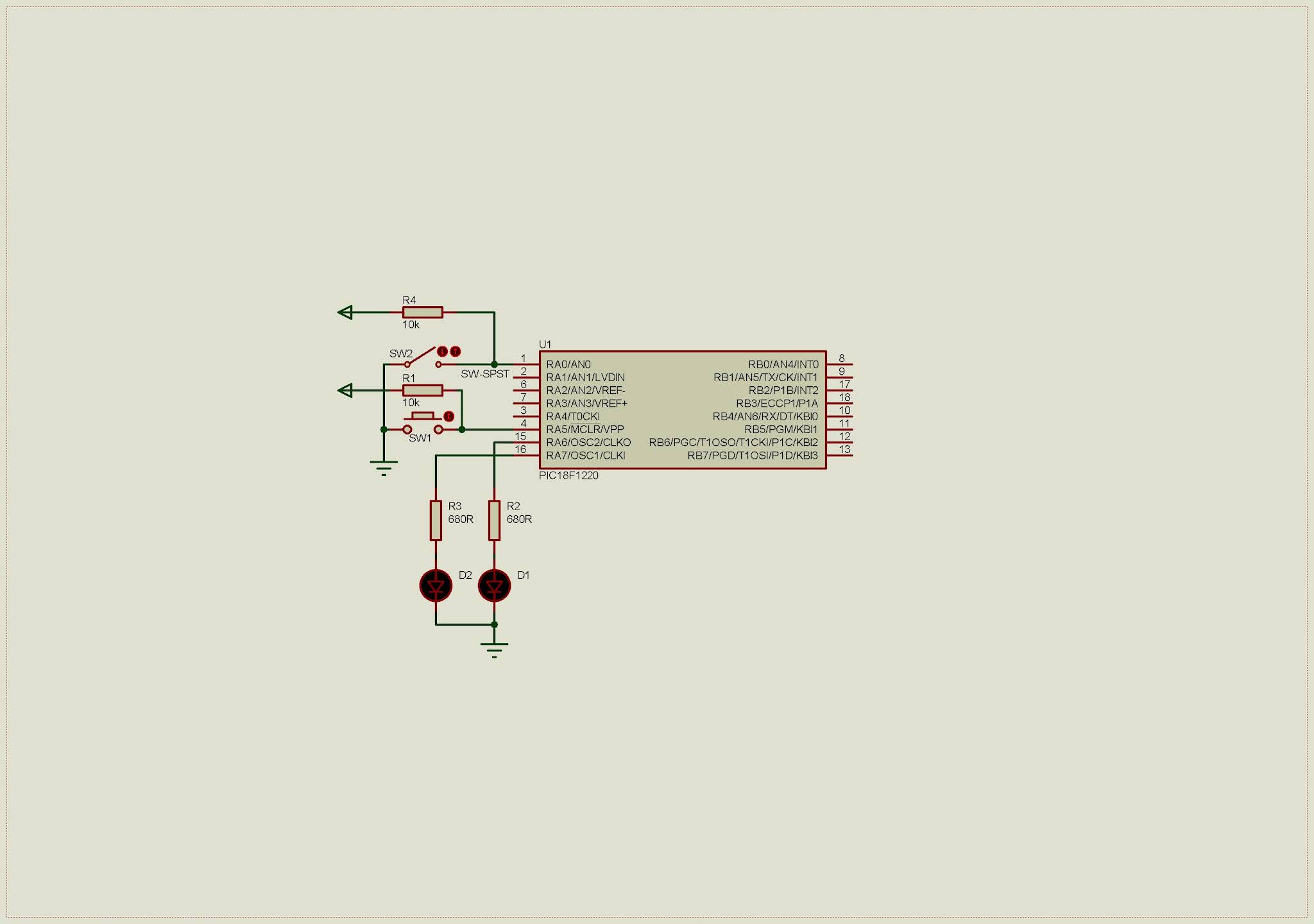
We want to test selected 4MHz internal oscillator. LED connects to RA7 blinks at a specific rate. A push button connects to RA0 toggles an output LED on RA6 whenever it’s pressed.
Schematic Diagram
Since internal oscillator is used, there is no requirement to add external crystal oscillator.
Schematic Diagram
C Programming
Port A is multiplexed with analog input function. User needs to disable this feature to make this port as a solely digital I/O.
C
/*
* PIC18F1220 internal RC oscillator
* and its I/O
*/
#include <xc.h>
#include "config.h"
#define _XTAL_FREQ 4000000
voidmain(void){
/*Select 4MHz internal oscillator*/
OSCCONbits.IRCF=0x06;
/*Clear IO*/
PORTA=0x00;
LATA=0x00;
/*Disable analog input function*/
ADCON1=0x7F;
/*RA0 digital input*/
TRISA=0x01;
while(1){
RA7^=1;
LATA6=RA0;
__delay_ms(250);
}
}
Configuration bits contain setting for this controller especially internal oscillator setting. We choose internal oscillator with I/O function on both RA6 and RA7.
C
// PIC18F1220 Configuration Bit Settings
// CONFIG1H
#pragma config OSC = INTIO2 // Oscillator Selection bits (Internal RC oscillator, port function on RA6 and port function on RA7)
#pragma config FSCM = ON // Fail-Safe Clock Monitor Enable bit (Fail-Safe Clock Monitor enabled)
#pragma config IESO = ON // Internal External Switchover bit (Internal External Switchover mode enabled)
// CONFIG2L
#pragma config PWRT = OFF // Power-up Timer Enable bit (PWRT disabled)
#pragma config BOR = ON // Brown-out Reset Enable bit (Brown-out Reset enabled)
// BORV = No Setting
// CONFIG2H
#pragma config WDT = OFF // Watchdog Timer Enable bit (WDT disabled (control is placed on the SWDTEN bit))
#pragma config MCLRE = ON // MCLR Pin Enable bit (MCLR pin enabled, RA5 input pin disabled)
// CONFIG4L
#pragma config STVR = ON // Stack Full/Underflow Reset Enable bit (Stack full/underflow will cause Reset)
#pragma config LVP = ON // Low-Voltage ICSP Enable bit (Low-Voltage ICSP enabled)
// CONFIG5L
#pragma config CP0 = OFF // Code Protection bit (Block 0 (00200-0007FFh) not code-protected)
#pragma config CP1 = OFF // Code Protection bit (Block 1 (000800-000FFFh) not code-protected)
// CONFIG5H
#pragma config CPB = OFF // Boot Block Code Protection bit (Boot Block (000000-0001FFh) not code-protected)
#pragma config CPD = OFF // Data EEPROM Code Protection bit (Data EEPROM not code-protected)
// CONFIG6L
#pragma config WRT0 = OFF // Write Protection bit (Block 0 (00200-0007FFh) not write-protected)
#pragma config WRT1 = OFF // Write Protection bit (Block 1 (000800-000FFFh) not write-protected)
// CONFIG6H
#pragma config WRTC = OFF // Configuration Register Write Protection bit (Configuration registers (300000-3000FFh) not write-protected)
#pragma config WRTB = OFF // Boot Block Write Protection bit (Boot Block (000000-0001FFh) not write-protected)
#pragma config WRTD = OFF // Data EEPROM Write Protection bit (Data EEPROM not write-protected)
// CONFIG7L
#pragma config EBTR0 = OFF // Table Read Protection bit (Block 0 (00200-0007FFh) not protected from table reads executed in other blocks)
#pragma config EBTR1 = OFF // Table Read Protection bit (Block 1 (000800-000FFFh) not protected from table reads executed in other blocks)
// CONFIG7H
#pragma config EBTRB = OFF // Boot Block Table Read Protection bit (Boot Block (000000-0001FFh) not protected from table reads executed in other blocks)
Click here to download this programming example package.