Introduction
Clock source of PIC18F1220 is driven from external source or internal source. Using external crystal, clocking frequency is broad but it needs additional clocking circuitry and components.
 |
| Oscillator type |
External Crystal Oscillator
External clock source are Low Power (LP), Crystal/Resonator (XT), and High Speed (HS) crystal oscillator. Its frequency ranges from 32kHz to 20MHz.
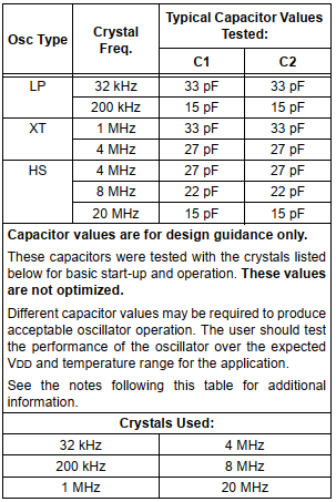 |
| Crystal oscillator and its capacitors value used |
Internal RC Oscillator
Internal oscillator is an inside RC oscillator that can be set in program. Its frequency ranges from 31kHz to 8MHz. To use this feature, programmer need to work with PIC18F1220 configuration bits, Oscillator Control Register, and Oscillator Tuning Register.
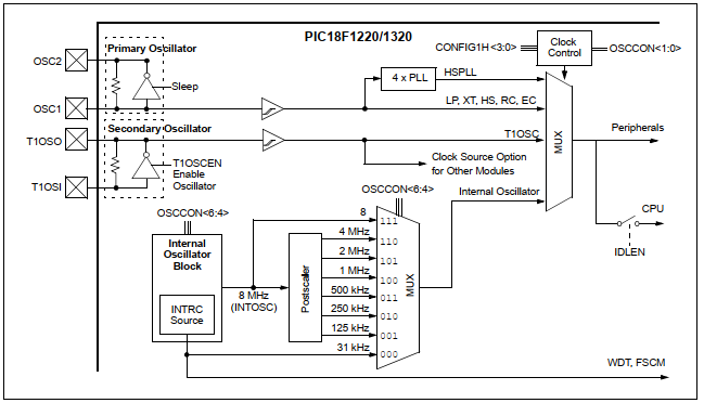 |
| Clock diagram of PIC18F1220 |
Using internal oscillator save components requirement, and on-board design space.
Setting Up in Program
Setting configuration bits of PIC18F1220 is a priority for internal oscillator.
Configuration Bits
There are up to 13 configuration registers in PIC18F1220. However CONFIGH1H (address 300001h) contains setting for internal oscillator.
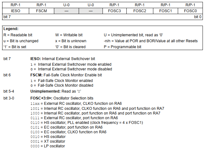 |
| CONFIG1H Configuration Register |
However in XC8 programmer use “#pragma config” directive. Programmer can select only internal oscillator only, or with I/O function on RA6 and RA7.
Registers Setting
There are two registers in SFR relate to internal oscillator.
Oscillator Tuning Registers – OSCTUNE
This register make a frequency tuning of internal oscillator between its lowest frequency and its highest frequency.
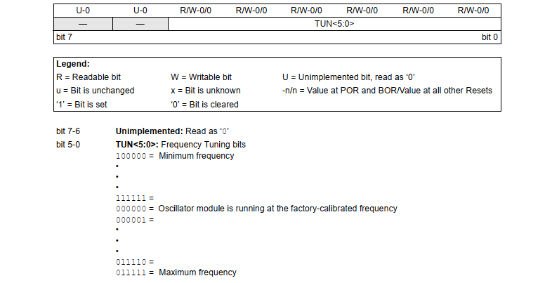 |
| Oscillator Tuning Registers – OSCTUNE |
Oscillator Control Register – OSCCON
This register set system clock mode, switch between discrete frequency of internal oscillator, and status checking.
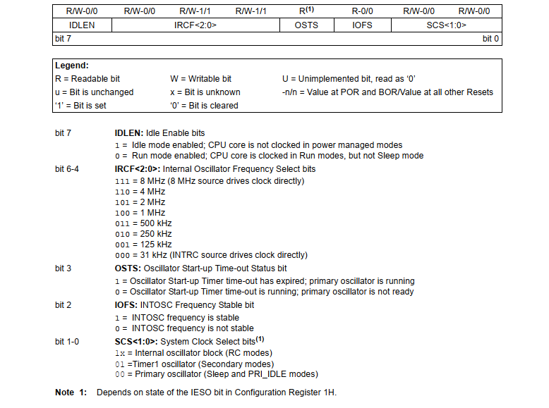 |
| Oscillator Control Register – OSCCON |
Programming Example
We want to test selected 4MHz internal oscillator. LED connects to RA7 blinks at a specific rate. A push button connects to RA0 toggles an output LED on RA6 whenever it’s pressed.
Schematic Diagram
Since internal oscillator is used, there is no requirement to add external crystal oscillator.
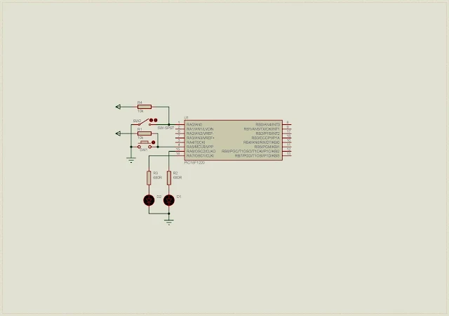 |
| Schematic Diagram |
C Programming
Port A is multiplexed with analog input function. User needs to disable this feature to make this port as a solely digital I/O.
Configuration bits contain setting for this controller especially internal oscillator setting. We choose internal oscillator with I/O function on both RA6 and RA7.
Click here to download this programming example package.
No comments:
Post a Comment