A typical digital display device is 7-Segments display. It’s very easy to program and interface to digital IC, or microcontroller for novice learner.
They come with different color and digit size. Common cathode and anode is a way to identify it. These two types are complement. Digital data inputs (7-Segments codes) to these two device type are different (complemented).
Voltage and current requirement for each segment are different depending on display’s digit-size. These parameters must be known as they are stated in device’s specification. Typically interfacing between digital controller and this device require a current limiting resistor for each segment.
AT89C52 typically supplied at +5V. So its digital output driving is +5V. We need to add a resistor between digital output pin of this controller and display.
 |
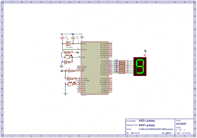
| Schematic diagram for program simulation |
AT89C52 operates at 12MHz from external crystal oscillator. P1.0 is a digital input. Whenever it’s pressed it increase value of counter. Controller counts up to 16. P2 interfaces to a single common anode type 7-Segments display.
C program is written in Keil IDE for 8051 device. Coding is very simple.
Click here to download this example package.

No comments:
Post a Comment