Wednesday, April 29, 2020

Controlling the bipolar stepper motor with ATMega32

Controlling the bi-polar stepper motor with ATMega32 Bipolar stepper motor give more precise stepping angle and higher torque. But the driving method is more difficult than the unipolar stepper motor.

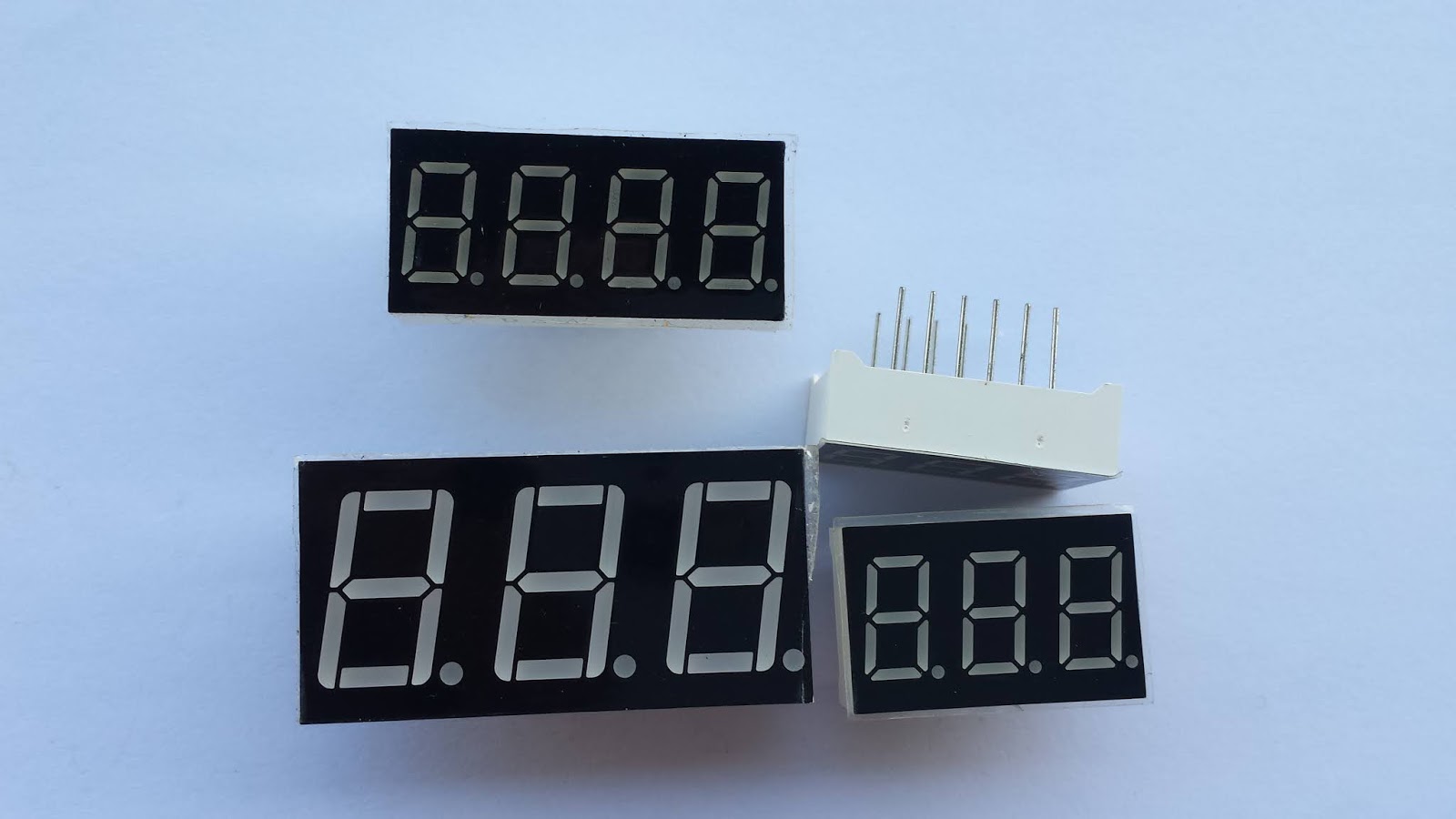
Bipolar stepper motor (Model 42BYGH34-0400A)  with 1.8 degree step angle.

It is made of two distinct coils, but each coil is separated a much as possible around the rotor, to make stepping angle much smaller.


Diagram of common bipolar stepper motor.
This motor come from the Chinese company as shown in the picture above.

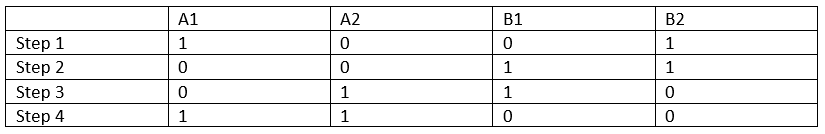
To make it step look at the time diagram below:

Timing Diagram for stepping clock wise and counter clock wise

Difference bipolar stepper motor has difference stepping angle. We can check its spec before use.

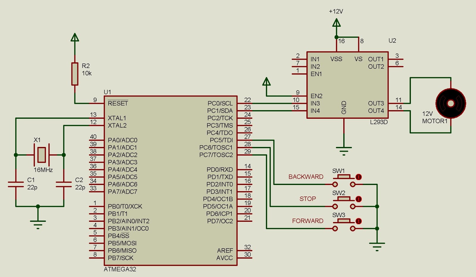
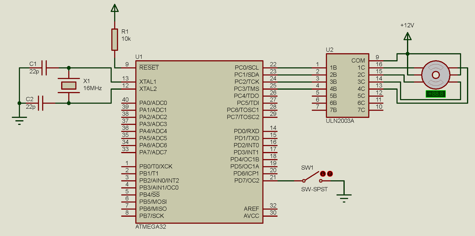
The example below just like the previous example. I use a switch connects to PD7 to control the stepping direction of the bipolar stepper motor.

A bipolar stepper motor connects to PORTC. PD7 is used for controlling
the direction.

Source code:

#include <avr/io.h>
#define F_CPU 16000000UL
#include "util/delay.h"
#define stepTime 100
//clock wise stepping
void stepCW(){
 PORTC=0b00001100;
 _delay_ms(stepTime);
 PORTC=0b00000110;
 _delay_ms(stepTime); 
 PORTC=0b00000011;
 _delay_ms(stepTime);
 PORTC=0b00001001;
 _delay_ms(stepTime);
}
//counter clock wise stepping
void stepCCW(){
 PORTC=0b00001001;
 _delay_ms(stepTime);
 PORTC=0b00000011;
 _delay_ms(stepTime);
 PORTC=0b00000110;
 _delay_ms(stepTime);
 PORTC=0b00001100;
 _delay_ms(stepTime);
}
int main(void)
{
    DDRC=0xFF;
 DDRD=0x7F;
 PORTD=0x80;
    while (1) 
    {
 if((PIND&0xFE)==0) stepCW();
 else stepCCW();
    }
}
Back to main tutorial page ATMega32 tutorials in C with Atmel Studio 7.

Tuesday, April 28, 2020

Controlling the uni-polar stepper motor with ATMega32

Uni-polar stepper motor is kind of brush-less DC motor that convert electrical pulse to mechanical movement. Comparing to bipolar stepper motor, it's easy to control but with lower torque. Stepper motor give a higher precision stepping than simple brushed DC motor. It's commonly use in photocopier machine, numerical control etc.

Different size of Uni-polar Stepper Motor 

It is made of two distinct coils. Each coil divided into two pieces by a common centered tap.


Unipolar Stepper Motor internal diagram.
Two distinct coil make four coil, A1, A2, B1, B2.
 We can rotate by two method, half stepping and full stepping.

Half Stepping

Half stepping is very easy to implement. Since the motor made of four coil, we just active each coil one by one. For Example, we activate A1 Coil for a given millisecond and then turn A1 off. After that we do this to the next A2 coil.

This stepping method could be easily implemented using a synchronous digital circuit.

The timing diagram below used for stepping counter clock wise:
Timing Diagram For Counter Clock Wise Half Stepping

The time diagram below used for stepping clock wise:

Timing Diagram For Clock Wise Stepping

The example below I use a switch to set the direction of half stepping.

ATMega32 controlling the direction of unipolar stepper motor

Source Code of this half stepping example could be download here:

#include <avr/io.h>
#define F_CPU 16000000UL
#include "util/delay.h"
#define stepTime 50

 void stepBackward(){
 PORTC=0x01;
 _delay_ms(stepTime);
 PORTC=0x02;
 _delay_ms(stepTime);
 PORTC=0x04;
 _delay_ms(stepTime);
 PORTC=0x08;
 _delay_ms(stepTime);
 }
 void stepForward(){
 PORTC=0x08;
 _delay_ms(stepTime);
 PORTC=0x04;
 _delay_ms(stepTime);
 PORTC=0x02;
 _delay_ms(stepTime);
 PORTC=0x01;
 _delay_ms(stepTime);
 }
 int main(void)
 {
     DDRC=0x0F; //PC0.3 ARE OUTPUT
 PORTC=0x00; //Clear PortC
 DDRD=0x7F;  //PD7 IS INPUT
 PORTD=0x80; //PULLUP PD7 HIGH
     while (1) 
     {
 if(PIND&0x80) stepBackward();
 else stepForward();
     }
 }

Full Stepping

Full stepping give the motor to maximize its output torque. For this stepping, we must active two coil at the same time to make one step.

The timing diagram below gives the full step clock wise rotation:

Full step clock wise rotation timing diagram

The timing diagram below gives the full step counter clock wise rotation:

Full step counter clock wise rotation timing diagram

I repeat the above example, but with full stepping. The schematic remain the same, but I modify the source code for full stepping.

Source Code for full stepping could be downloaded here:

#include <avr/io.h> 

#define F_CPU 16000000UL 
#include "util/delay.h" 
#define stepTime 50 
 void stepForward(){ 
 PORTC=0b1001; 
 _delay_ms(stepTime); 
 PORTC=0x0011; 
 _delay_ms(stepTime); 
 PORTC=0b0110; 
 _delay_ms(stepTime); 
 PORTC=0b1100; 
 _delay_ms(stepTime); 
 } 
 void stepBackward(){ 
 PORTC=0b1100; 
 _delay_ms(stepTime); 
 PORTC=0b0110; 
 _delay_ms(stepTime); 
 PORTC=0b0011; 
 _delay_ms(stepTime); 
 PORTC=0b1001; 
 _delay_ms(stepTime); 
 } 
 int main(void) 
 { 
 DDRC=0x0F; //PC0.3 ARE OUTPUT 
 PORTC=0x00; //Clear PortC 
 DDRD=0x7F;  //PD7 IS INPUT 
 PORTD=0x80; //PULLUP PD7 HIGH 
 while (1) 
 { 
 if(PIND&0x80) stepBackward(); 
 else stepForward(); 
 } 
 } 
Back to main tutorial page ATMega32 tutorials in C with Atmel Studio 7.

Monday, April 27, 2020

ATMega32 digital counter using external interrupt and multiplexed display

In the previous example, we discuss about the external interrupt of ATMega32 and interfacing the digital output to seven segments display.

Now we drive into an simple application of making a digital counter that could drive up to 4 digits with only one port and four control signals.

multiplexed seven segments display of any digits

Multiplexed seven segments display is made of multi digit. Each digit share the same LED segments, but distinct common.

NFD-5641Ax multiplexed seven segment display.
It has four digit common cathode. It has only one segment port,
but different common pin for each digit.

We use multiplexing method to cut down the number of port's pin to drive a multi-digits display.

Multiplexing a display is very simple to explain:

  1. Clear all common pins of all digit
  2. Output LED data to LED segments
  3. Enable a specific digit's common pin (for common cathode display, put that common to Low) 
  4. Wait for about 10 ms
  5. Repeat all step above.    
Practically, we can multiplex up to 8 digits.

In this example, I use three external interrupt pins:
  • INT0 for count down
  • INT1 for reset
  • INT2 for count up
The four-digit counter could count up to 10000 value.
Schematic for simulation
In real world, we have to add power supply pin +5 V and GND.
Four digit multiplexed seven segments display common anode type, commonly 0.56 inches size.

Source code and design file could be download here:

/* 
* interruptCounter.c
*
* Created: 4/27/2020 5:21:19 PM
* Author : aki-technical
*/

#include <avr/io.h>
#include "avr/interrupt.h"

#define F_CPU 16000000UL
#include "util/delay.h"

unsigned int cnt=0;

void ssd(){
/*SEVEN SEGMENT MAP FOR COMMON
CATHODE TYPE SEVEN SEGMENT DISPLAY
*/
unsigned char ssd[16]={0x3F,0x06,0x5B,0x4F,0x66,0x6D,0x7D,
0x07,0x7F,0x6F,0x77,0x7C,0x39,0x5E,0x79,0x71};
//Digit 1 1000's
PORTD=0b00001100;
PORTC=ssd[cnt/1000];
PORTD=0b00011100;
_delay_ms(10);

//Digit 3 100's
PORTD=0b00001100;
PORTC=ssd[(cnt%1000)/100];
PORTD=0b00101100;
_delay_ms(10);

//Digit 2 10's
PORTD=0b00001100;
PORTC=ssd[(cnt%100)/10];
PORTD=0b01001100;
_delay_ms(10);

//Digit 1 1's
PORTD=0b00001100;
PORTC=ssd[cnt%10];
PORTD=0b10001100;
_delay_ms(10);

}
int main(void)
{
//PORTD IS OUTPUT
DDRC=0xFF;
//PD7.4 ARE OUTPUT CONTROL PIN
DDRD|=(1<<4)|(1<<5)|(1<<6)|(1<<7);
//PB2 USED FOR INT2
PORTB=(1<<2);
//INT0 AND INT1
PORTD=(1<<2)|(1<<3);
//SET EXTERNAL INTERRUPT FOR INT0, INT1 AND INT1
GICR=(1<<7)|(1<<6)|(1<<5);
//SET GLOBLE INTERRUPT
sei();
while (1)
{
ssd();
}
}

/*
Interrupt Service Routine for
Interrupt0
*/
ISR(INT0_vect){
if(cnt>0) cnt--;
}

/*
Interrupt Service Routine for
Interrupt1
*/
ISR(INT1_vect){
cnt=0;
}

/*
Interrupt Service Routine for
Interrupt2
*/
ISR(INT2_vect){
if(cnt<10000) cnt++;
}


Back to main tutorial page ATMega32 tutorials in C with Atmel Studio 7.

Sunday, April 26, 2020

ATMega32 External Interrupt Example

External interrupt is an external notification to the micro-controller. Usually, an external event (sense) such as logic changing, or edge triggering.

In ATMega32, there are three external interrupt source, INT0, INT1 and INT2. Each source locate at different pins.

  1. INT0 at PD2
  2. INT1 at PD3
  3. INT2 at PB2
For events could trigger the interrupt:
  1. Low logic level
  2. Logic changing
  3. Falling edge
  4. Rising Edge

To program the interrupt, set up the code in the following step:

  1. Set the interrupt input pin as digital input
  2. Enable the interrupt for the corresponding input
  3. Enable the global interrupt control
  4. Keep your main program loop working
  5. Write the interrupt service routine to handle the corresponding interrupt

In ATMega32 the external interrupt is controlled by the GICR (General Interrupt Control Register).


General Interrupt Control Register

We enable any external interrupt by giving "1" to the source. For example, external interrupt 1 is enabled by setting INT1=1.

Interrupt flag contain the information about the state of any presenting interrupt. GIFR (General Interrupt Flage Register) store the status of external interrupts.


GIFR (General Interrupt Flag Register)

We can test any each external interrupt flag of this register to find the interrupt source. For example, we find INTF1=1, that mean that external interrupt INT1 is occur.

There are four modes of event (sense) the trigger the interrupt, as mention about. Those senses are controlled in the MCU Control Register (MCUCR).


ATMega32 External Interrupt Example
MCUCR (MCU Control Register)

The ISC11 and ISC10, are the interrupt sense control of INT1.

The ISC01 and ISC00, are the interrupt sense control of INT0

There four mode of sense as refers to the datasheet. By default, they sense Low to trigger interrupt.


The Interrupt Service Routine (ISR) is a block of source code uses for handling the interrupt. They are short because the interrupt must not take to long to complete.

The ISR locates at the interrupt vector. Each interrupt source has their own interrupt vector. For example INT0_vect is an interrupt vector for external interrupt 0.


In this example, I use all three external interrupt sources. The interrupt sense is logic low. So when I make any external interrupt pin low, it will generate the interrupt. The ISR is to toggle LED output each corresponding to the source.


Schematic and Simulation Diagram.
We have external interrupt, INT0, INT1 and INT2
connect to its individual active low push button.
Each interrupt toggles the corresponding output LEDs. 

Source code:

  1. #include <avr/io.h>
  2. #include "avr/interrupt.h"
  3.  
  4. int main(void)
  5. {
  6. //PA7.5 ARE OUTPUT
  7. DDRA=(1<<5)|(1<<6)|(1<<7);
  8. //PB2 USED FOR INT2
  9. PORTB=(1<<2);
  10. //INT0 AND INT1
  11. PORTD=(1<<2)|(1<<3);
  12. //SET EXTERNAL INTERRUPT FOR INT0, INT1 AND INT1
  13. GICR=(1<<7)|(1<<6)|(1<<5);
  14. //SET GLOBLE INTERRUPT
  15. sei();
  16. while (1)
  17. {
  18. }
  19. }
  20.  
  21. /*
  22.  Interrupt Service Routine for
  23.  Interrupt0
  24.  */
  25. ISR(INT0_vect){
  26. //Toggle PA5
  27. PORTA^=(1<<5);
  28. }
  29.  
  30. /*
  31.  Interrupt Service Routine for
  32.  Interrupt1
  33.  */
  34. ISR(INT1_vect){
  35. //Toggle PA6
  36. PORTA^=(1<<6);
  37. }
  38.  
  39. /*
  40.  Interrupt Service Routine for
  41.  Interrupt2
  42.  */
  43. ISR(INT2_vect){
  44. //Toggle PA7
  45. PORTA^=(1<<7);
  46. }

Back to main tutorial page ATMega32 tutorials in C with Atmel Studio 7.

Click here to download this example.

If you want a standard PCB for ATMega32 micro-controller, you can order my AVR Microcontroller project from PCBWay with a reasonable price. Click here to get a free $5 credit for new account.

Interfacing ATMega32 to 74HC595 shift register
ATMega16 ATMega32 Experiment Board PCB from PCBWay


Interfacing ATMega32 To Seven Segment Display


Seven Segment Display (SSD) is a classical display device for low end digital electronic equipment. The programming for is very simple. It could represent numbers and some English letters.

It come with two terminology, common cathode type and common anode type. But deciding which type to use depends on the application. In this example, I take only common cathode type.

Single digit seven segments display
single digit seven segments display

LED segments configurations
Segment LED diagram


Since it made of seven LED segment, we just turn on any LED to display digit or letter. For example, turning on LED segment B and C make digit "1" to display.

In programming, they commonly use hexadecimal equivalent to the SSD output.

For the common cathode type display the hex code represent the digit from 0 to 9 and from A to F is shown below:


Each LED segment made of from LED, requiring around 2 V and ~10 mA of current. Typically, the digital output from microcontroller drives a voltage of +5V TTL. So we need to cut down the voltage from microcontroller to ~2 V via resistor.


Resistors are connected to cut down voltage output to common cathode SSD

In this example, I use a digital input from PD0 to count the event, and output the counting to the presented SSD.


Circuit diagram uses for simulation

Source Code:
  1. #include <avr/io.h>
  2. #define F_CPU 16000000UL
  3. #include "util/delay.h"
  4. //SET THE INPUT BUTTON FOR COUNTING
  5. #define btnPressed ((PIND&0x01)==0)
  6. int main(void)
  7. {
  8. //SEVEN SEGMENT MAP FOR COMMON
  9. //CATHODE TYPE SEVEN SEGMENT DISPLAY
  10. unsigned char ssd[16]={0x3F,0x06,0x5B,0x4F,0x66,0x6D,0x7D,
  11. 0x07,0x7F,0x6F,0x77,0x7C,0x39,0x5E,0x79,0x71};
  12. unsigned char btnCount=0;
  13. DDRC=0xFF; //PORTC IS FOR OUTPUT TO SEVEN SEGMENT
  14. DDRD=0xFE; //PORTD PD0 IS USED FOR INPUT COUNTING
  15. PORTD=0x01; //SET PD0 TO HIGH FOR PULLING UP
  16. while (1)
  17. {
  18. if (btnPressed) //CHECK IF PD0 IS PRESSED
  19. {
  20. btnCount+=1; //Increase The Counter
  21. _delay_ms(250);
  22. if(btnCount>15) btnCount=0;
  23. //RESET COUNTER WHEN IT IS OVER 15
  24. }
  25. PORTC=ssd[btnCount]; //OUTPUT TO SSD
  26. }
  27. }

Back to main tutorial page ATMega32 tutorials in C with Atmel Studio 7.

Click here to download this example.

If you want a standard PCB for ATMega32 micro-controller, you can order my AVR Microcontroller project from PCBWay with a reasonable price. Click here to get a free $5 credit for new account.

Interfacing ATMega32 to 74HC595 shift register
ATMega16 ATMega32 Experiment Board PCB from PCBWay
 

ATMega32 Controlling A DC Servo Motor Without PWM Module

A DC servo motor comes with an electronic hardware control, to rotate to any specific angle. Typically, It can rotate between -90 degrees to +90 degrees.

A simple mini servo motor
The SG90 simple servo motor

Servo Angle Positioning

It come with three pins, in which two pins for supply voltage, the last one is for DC control signal.
The control signal is a square wave with the amplitude of 5 V. Typically, it accept a frequency of 50 Hz. The angle positioning is made by the High time varies from 1 ms to 2 ms.

Servo timing diagram
1 ms to 2 ms duty makes -90 degree to +90 degree angle rotation.
In this example, I use delay function in GCC C for AVR to make timing signal.

Schematic Diagram. A servo motor connects to PB0.
PC0.3 connect to the switches controlling the angle of servo.

Servo is controlled by output signal from PB0. I use three button to control the servo angle to -90 degree, 0 degree and +90 degree.

Source code could be download here.

/*
  * servoExample_1.c
  *
  * Created: 4/26/2020 9:10:13 AM
  * Author : bonTha
  */ 
 #include <avr/io.h>
 #define F_CPU 16000000UL
 #include "util/delay.h"
 #define rotate__90 (PINC&0x01)
 #define rotate_0 (PINC&0x02)
 #define rotate_90 (PINC&0x04)
 void servoRotate(short angle){
 switch(angle){
 case -90:
 PORTB=0x01;
 _delay_us(1000);
 PORTB=0x00;
 _delay_us(19000);
 break;
 case 0:
 PORTB=0x01;
 _delay_us(1500);
 PORTB=0x00;
 _delay_us(18500);
 break;
 case 90:
 PORTB=0x01;
 _delay_us(2000);
 PORTB=0x00;
 _delay_us(18000);
 break;
 default:
 break;
 }
 }
 int main(void)
 {
 DDRB=0x01; //PB0 IS OUTPUT
 DDRC=0xF8; //PC0.2 ARE INPUT 
 PORTC=0x07;
     while (1) 
     {
 if(rotate__90==0) servoRotate(-90);
 else if(rotate_0==0) servoRotate(0);
 else if(rotate_90==0) servoRotate(90);
     }
 }

Back to main tutorial page ATMega32 tutorials in C with Atmel Studio 7.

If you want a standard PCB for ATMega32 micro-controller, you can order my AVR Microcontroller project from PCBWay with a reasonable price. Click here to get a free $5 credit for new account.

Interfacing ATMega32 to 74HC595 shift register
ATMega16 ATMega32 Experiment Board PCB from PCBWay


Saturday, April 25, 2020

ATMega32 controlling DC Motor direction via buttons

This is another digital input output of ATMega32. In this example I use a single Port of PORTC accepting the digital input from button, and output the control to DC motor.

I use L293 for controlling the direction, and also driving the motor at higher voltage and higher current at +12 V.

Three input buttons are Forward, Stop and Backward. Motor is controlled by PC0 and PC1 pin on the same port.


Source Code:


/*
 * controllingMotorStartStop.c
 *
 * Created: 4/25/2020 8:00:39 PM
 * Author : aki-technical
 */ 
#include <avr/io.h>
#define F_CPU 16000000UL
#include "util/delay.h"
//Test the  PINC7 
#define forward (PINC&0b10000000)
//Test the PINC6
#define stop    (PINC&0b01000000)
//Test the PINC5
#define backward (PINC&0b00100000)
//OUTPUT DATA FOR MOTOR
#define run_forward 0b11100001
#define run_backward 0b11100010
#define stop_running 0b11100000

int main(void)
{
    DDRC=0b00011111; //PINC7.5 INPUT
    PORTC=0b11100000; //PC7.5 SET TO HIGH
    /* Replace with your application code */
    while (1) 
    {
        if (forward==0)
        {
            PORTC=stop_running;
            _delay_ms(250);
            PORTC=run_forward;
        }
        else if (stop==0)
        {
            PORTC=stop_running;
            _delay_ms(250);
            PORTC=stop_running;
        }
        else if (backward==0)
        {
            PORTC=stop_running;
            _delay_ms(250);
            PORTC=run_backward;
        }
    }
}

Back to main tutorial page ATMega32 tutorials in C with Atmel Studio 7.

ATMega32 using a single port for input and output

In the previous example, I show an example of digital input output programming using distinct port.Now I show how to use a single port for for bot input and output. The overall operation of the program just like the previous one. So I just modify the port.

PORTC is used for both input and output

Source is written using Atmel Studio 7:
/*
 * setResetSinglePort.c
 *
 * Created: 4/25/2020 7:27:50 PM
 * Author : admin
 */ 
#include <avr/io.h>
#define setButton (PINC&0b10000000)
#define resetButton (PINC&0b01000000)
int main(void)
{
    DDRC=0b00111111; // PC7 AND PC6 ARE INPUT
    PORTC=0b11000000; //SET PULLUP HIGH FOR PC7 AND PC6
    /* Replace with your application code */
    while (1) 
    {
        if (setButton==0) PORTC=0b11000001;
        if (resetButton==0)  PORTC=0b11000000;
    }
}
Back to main tutorial page ATMega32 tutorials in C with Atmel Studio 7.


ATMega32 how to set and reset relay via digital buttons

In this example, I use digital inputs outputs of ATMega32 to control a relay. Relay has an advantage of driving alternative that the microcontroller could do that directly.

The CPU clocks at 16 MHz, supplied at +5 V DC.

Simulation Schematic, The system controlled by ATMega32 AVR

PC0 of PortC is a digital output, driving a relay. The relay coil work at +5V. You can choose another voltage rating.
PA0 is an input, connected to a push button sw1. When the button is pressed, PC0 become set.
PA7 is an input, connected to a push button sw2. When the button is pressed, PC0 become reset.

Source code is written in Atmel Studio 7 with AVR GCC.

/*
 * setResetButton.c
 *
 * Created: 4/25/2020 5:23:29 PM
 * Author : balangKash
 */ 
#include <avr/io.h>
#define setButton (PINA&0x01)
#define resetButton (PINA&0x80)
int main(void)
{
    DDRA=0x7E; //PA0 and PA7 are input
    PORTA=0x81; //Set PA0 and PA7 High
    DDRC=0xFF;
    /* Replace with your application code */
    while (1) 
    {
        if (setButton==0) PORTC=0x01;
        if (resetButton==0)    PORTC=0x00;
    }
}

Back to main tutorial page ATMega32 tutorials in C with Atmel Studio 7.

Search This Blog

Labels

25AA010A (1) 8051 (7) 93AA46B (1) ADC (30) Analog Comparator (1) Arduino (15) ARM (6) AT89C52 (7) ATMega32 (54) AVR (57) CCS PICC (28) DAC (1) DHT11 (2) Display (105) Distance Sensor (3) DS18B20 (3) dsPIC (2) dsPIC30F1010 (2) EEPROM (5) Environment Sensor (4) esp8266 (1) I2C (29) Input/Output (67) Interrupt (19) Keil (5) Keypad (10) LCD (46) Master/Slave (1) MAX7221 (1) MCP23017 (5) MCP23S17 (4) Meter (3) MikroC (2) Motor (15) MPLABX (66) Nokia 5110 LCD (3) OLED (2) One-Wire (6) Oscillator (8) PCB (6) PCD8544 (3) PCF8574 (5) PIC (107) PIC12F (2) PIC16F628A (2) PIC16F630 (1) PIC16F716 (3) PIC16F818 (10) PIC16F818/819 (2) PIC16F84A (15) PIC16F876A (1) PIC16F877A (9) PIC16F88 (1) PIC16F887 (60) PIC18 (19) PIC18F1220 (4) PIC18F2550 (3) PIC18F4550 (12) PWM (11) RTC (8) Sensor (10) SH1106 (1) Shift Register (11) Shift Registers (2) SPI (24) STM32 (6) STM32 Blue Pill (6) STM32CubeIDE (6) STM32F103C8T6 (6) SysTick (3) temperature sensor (11) Thermometer (21) Timer/Counter (30) TM1637 (2) UART (7) Ultrasonic (4) Voltmeter (7) WDT (1) XC16 (2) XC8 (94)