Now we drive into an simple application of making a digital counter that could drive up to 4 digits with only one port and four control signals.
 |
| multiplexed seven segments display of any digits |
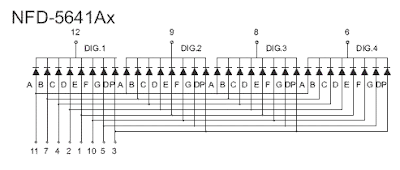
Multiplexed seven segments display is made of multi digit. Each digit share the same LED segments, but distinct common.
 |
| NFD-5641Ax multiplexed seven segment display. It has four digit common cathode. It has only one segment port, but different common pin for each digit. |
We use multiplexing method to cut down the number of port's pin to drive a multi-digits display.
Multiplexing a display is very simple to explain:
- Clear all common pins of all digit
- Output LED data to LED segments
- Enable a specific digit's common pin (for common cathode display, put that common to Low)
- Wait for about 10 ms
- Repeat all step above.
Practically, we can multiplex up to 8 digits.
In this example, I use three external interrupt pins:
- INT0 for count down
- INT1 for reset
- INT2 for count up
The four-digit counter could count up to 10000 value.
 |
| Schematic for simulation In real world, we have to add power supply pin +5 V and GND. Four digit multiplexed seven segments display common anode type, commonly 0.56 inches size. |
Source code and design file could be download here:
/*
  * interruptCounter.c
  *
  * Created: 4/27/2020 5:21:19 PM
  * Author : aki-technical
  */

 #include <avr/io.h>
 #include "avr/interrupt.h"

 #define F_CPU 16000000UL
 #include "util/delay.h"

 unsigned int cnt=0;

 void ssd(){
 /*SEVEN SEGMENT MAP FOR COMMON
 CATHODE TYPE SEVEN SEGMENT DISPLAY
 */
 unsigned char ssd[16]={0x3F,0x06,0x5B,0x4F,0x66,0x6D,0x7D,
 0x07,0x7F,0x6F,0x77,0x7C,0x39,0x5E,0x79,0x71};
 //Digit 1 1000's
 PORTD=0b00001100;
 PORTC=ssd[cnt/1000];
 PORTD=0b00011100;
 _delay_ms(10);

 //Digit 3 100's
 PORTD=0b00001100;
 PORTC=ssd[(cnt%1000)/100];
 PORTD=0b00101100;
 _delay_ms(10);

 //Digit 2 10's
 PORTD=0b00001100;
 PORTC=ssd[(cnt%100)/10];
 PORTD=0b01001100;
 _delay_ms(10);

 //Digit 1 1's
 PORTD=0b00001100;
 PORTC=ssd[cnt%10];
 PORTD=0b10001100;
 _delay_ms(10);

 }
 int main(void)
 {
 //PORTD IS OUTPUT
 DDRC=0xFF;
 //PD7.4 ARE OUTPUT CONTROL PIN
 DDRD|=(1<<4)|(1<<5)|(1<<6)|(1<<7);
 //PB2 USED FOR INT2
 PORTB=(1<<2);
 //INT0 AND INT1
 PORTD=(1<<2)|(1<<3);
 //SET EXTERNAL INTERRUPT FOR INT0, INT1 AND INT1
 GICR=(1<<7)|(1<<6)|(1<<5);
 //SET GLOBLE INTERRUPT
 sei();
 while (1)
 {
 ssd();
 }
 }

 /*
 Interrupt Service Routine for
 Interrupt0
 */
 ISR(INT0_vect){
 if(cnt>0) cnt--;
 }

 /*
 Interrupt Service Routine for
 Interrupt1
 */
 ISR(INT1_vect){
 cnt=0;
 }

 /*
 Interrupt Service Routine for
 Interrupt2
 */
 ISR(INT2_vect){
 if(cnt<10000) cnt++;
 }
Back to main tutorial page ATMega32 tutorials in C with Atmel Studio 7.
No comments:
Post a Comment