728x90

728x90

Showing posts with label PWM. Show all posts

Wednesday, February 17, 2021

Arduino rotates a small servo motor with buttons


A servo is a kind of motor built in a module. The module contains a DC motor and a feed back control circuit. The feed back circuit regulates the motor rotating position to a specific angle receives from its master MCU, for example and Arduino.

Arduino rotates a small servo motor with buttons
Picture of this example

Controlling the position needs a specific timing. Conventionally, the signal timing frequency is 50 Hz. For more information about the servo motor timing, see this post

Servo motors are available in many physical sizes and interfaces. Choosing a servo motor depends on the application. With Arduino, there are many libraries to interface with external hardware module, including the servo motor. The Servo.h is already available after the installing of Arduino IDE. Servo control pin can be any where within the digital I/O pin and it's selected by source code writing.

To use the servo library we must #include <Servo.h>. Additionally, we must create a servo object, for example,

Servo sg90;

Using a very simple servo motor like the SG90 requires a few methods.

  1. attach() - sg90.attach(pin) : where pin is any pin on the Arduino board in use.
  2. write() - sg90.write(angle): where angle is between 0 and 190 degree.

Other sophisticated  servo motors have an angle reading line. But we don't need it here, as a simple example.

Arduino rotates a small servo motor with buttons
SG90 servo from device's specification

A typical servo SG90 has three lines - GND, VCC and Control. Control and VCC line requires a +5V pulse. Control line is the orange one's. It's no other than a PWM signal with low frequency.
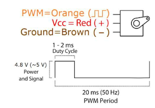
Arduino rotates a small servo motor with buttons
SG90 pin diagram and its timing from the device's specification

In this example post, I use three tactile switches to rotate a SG90 servo motor with three corresponding angles 0 , 90 and 180 degrees respectively. I use four pin A0, A1, A2 and A3. 
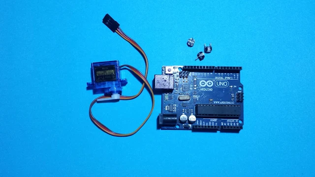
Arduino rotates a small servo motor with buttons
Some required parts

Arduino rotates a small servo motor with buttons
Connections Diagram

Arduino code from Github gist lists below.


Click here to download Arduino sketch.
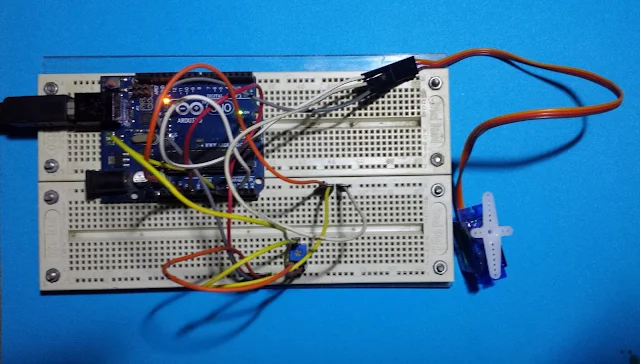
Arduino rotates a servo motor using a potentiometer

In the previous post, I use three tactile switches to rotate a servo motor to three angle positions. However, using a potentiometer, we can continuously rotates the angle of servo motor in accordance to the adjustment of the potentiometer. 

Arduino rotates a servo motor using a potentiometer
A picture of this example

With the  Arduino Servo.h and analogRead function, this task could be done easily. In this example, a potentiometer connects to pin A0 work as an analog input adjusting the angle of rotation. A servo again, connects to pin A3.

Arduino rotates a servo motor using a potentiometer
Connections Diagram

The analogRead() function return a 10-bit (1024) value from any reading from a specific analog input pin. Hence, this analog value must convert from 1024 to 180 in degree. This could be done by a simple equation as will be shown in source code.

Click here to download the sketch archive of this example.

Friday, February 12, 2021

ATMega32 Timer/Counter1 in Fast PWM Mode

Introduction

Timer/Counter1 module of ATMega32 is configurable to operate in fast Pulse Width Modulation (PWM) mode. There are two PWM blocks inside this module - PWM A and PWM B. Hence there are two corresponding output pins for these two blocks - OC1A and OC1B.

PWM output pulse has two mode, non-inverting and inverting mode. Its set and clear output pulse is the comparison between TCNT1 and OC1X register (OC1A or OC1B).

ATMega32 Timer/Counter1 in Fast PWM Mode
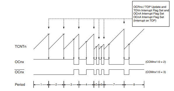
Fast PWM Mode - Timing Diagram

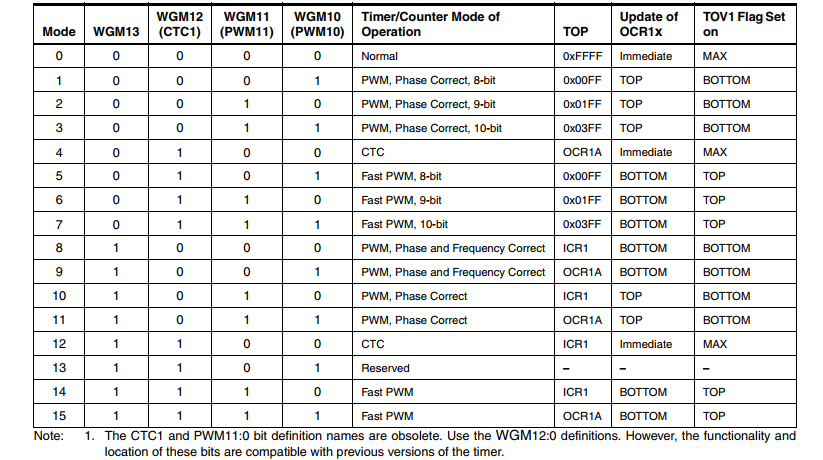
To make ATMega32 operates in this mode, user must set WGM13:0 of  Timer/Counter1 Control Register (TCCR1x) to 5, 6, 7, 14, or 15. Its frequency is calculated as below.

ATMega32 Timer/Counter1 in Fast PWM Mode
Fast PWM Mode Frequency

Its resolution is between 8 and 10-bit. Where,

ATMega32 Timer/Counter1 in Fast PWM Mode
Fast PWM Resolution

Programming

We need to configure some registers for fast PWM mode.
  • Timer/Counter1 Control Register A (TCCR1A)
ATMega32 Timer/Counter1 in Fast PWM Mode
TCCR1A

This register contains some settings for fast PWM mode. Compare Output Mode bits used for selecting between inverting and non-inverting mode of fast PWM mode.

ATMega32 Timer/Counter1 in Fast PWM Mode
Compare Output Mode Bits of TCCR1A

Waveform Generation Mode Bits must be set to any value as listed to make this module operates in fast PWM mode.

ATMega32 Timer/Counter1 in Fast PWM Mode
Waveform Generation Mode Bits

  • Timer/Counter1 Control Register B (TCCR1B)
This register contains prescaler selection for fast PWM mode. 
ATMega32 Timer/Counter1 in Fast PWM Mode
TCCR1B

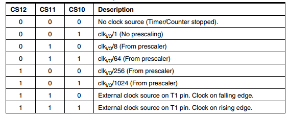
Clock Select Bits (CS12:10) allow user to set its prescaler effecting output frequency of fast PWM.

Timer/Counter1 Control Register B (TCCR1B)
Clock Selection Bits
  • Output Compare Register A 
This is a pair of 8-bit registers - OCR1AH and OCR1AL. This register is a compare variable of TCNT1 that toggle output waveform of PWM signal.
ATMega32 Timer/Counter1 in Fast PWM Mode
Output Compare Register A
Now we make a simple example of using fast PWM. PWM A generates its output waveform on OC1A pin with a frequency of 490Hz, and 50% duty cycle. Output signal is non-inverting mode. Its resolution is 8-bit.

ATMega32 Timer/Counter1 in Fast PWM Mode
Schematic Diagram

Microcontroller clock is 16MHz from external crystal oscillator.

Source Code:

/*
 * timer_1_fast_pwm_8_bit_1.c
 *
 * Created: 2/10/2021 3:41:04 PM
 * Author : admin
 */ 

#include <avr/io.h>

int main(void)
{
/*OC1A PD5 Output*/
DDRD|=(1<<5);
/*Non-inverting mode, fast PWM 8-bit*/
TCCR1A=(1<<COM1A1)|(1<<COM1B1)|(1<<WGM12)|(1<<WGM10);
/*1:64 Prescaler*/
TCCR1B=(1<<CS11)|(1<<CS10);
/*Select 50% duty cycle*/
OCR1AH=0;
OCR1AL=127;
    while (1) 
    {
    }
}

Click here to download archive. 

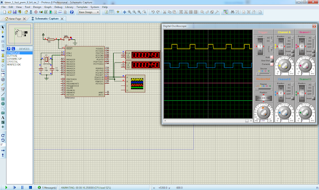
Now let use both of this PWM output of Timer/Counter1 module. Either OC1A and OC1B output signal are inverting with different duty cycle, but its frequency is unique. 

ATMega32 Timer/Counter1 in Fast PWM Mode
Simulation screen shot

Source code:

/*
 * timer_1_fast_pwm_8_bit_2.c
 *
 * Created: 3/3/2021 8:38:00 PM
 * Author : admin
 */ 

#include <avr/io.h>


int main(void)
{
    /*OC1A and OC1B Output*/
DDRD=(1<<5)|(1<<4);
/*inverting fast PWM 8-bit*/
TCCR1A=(1<<COM1A1)|(1<<COM1B1)|(1<<COM1A0)|(1<<WGM12)|(1<<WGM10);
/*1::64 Pre-Scaler*/
TCCR1B=(1<<CS11)|(1<<CS10);
/*OC1A duty cycle*/
OCR1AH=0;
OCR1AL=127;
/*OC1B duty cycle*/
OCR1BH=0;
OCR1BL=75;
    while (1) 
    {
    }
}

Click here to download this example.


Saturday, January 2, 2021

PIC18F4550 PWM Example in CCS PICC

Overview

Creating a varied analog voltage output from an MCU require an analog voltage generator, PWM (pulse width modulation). Making a analog voltage PWM to work, the user needs to know about all relevant register configurations to set the frequency and duty cycle of PWM signal.

However, in a high level embedded language, creating a PWM signal output doesn't need a deep level of low level hardware/register configuration. With a few C functions, the PWM signal output from any MCU could be created in a few minutes.

CCS PICC Basic Pulse Width Modulation Programming

Without using any technical detail of PWM software setting, we can create a PWM output from scratch with this compiler. In this introductory example, I use only a few C code to program the PWM.

  1. #use PWM directive
  2. pwm_set_duty_percent()
The directive #use PWM has many options, but I list a few commonly use options of this.
  • CCPx or PWMx - Select a CCP/PWM module
  • FREQUENCY=x - Set the frequency of PWM signal
  • PERIOD=x - Set the period of PWM signal
  • DUTY=x - The default duty cycle is 50% if it's not set.
For more details about this directive, check the compiler manual.

The pwm_set_duty_percent specifies the duty cycle of PWM output signal. The syntax is pwm_set_duty_percent(stream,value). Where stream is optional, and value is ranges from 0 to 1000. For example when value = 500, the PWM duty cycle is 50% and so on.

In this introductory example, I set a fixed frequency of PWM and a variable duty cycle. Duty cycle is adjusted by the variation of a POT. CCP1 is selected to make the PWM signal.

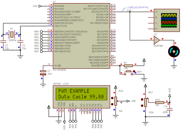
CCS PICC basic PWM example with PIC18F4550
I adjust the POT to the MAX.

C Source Code


Schematic 

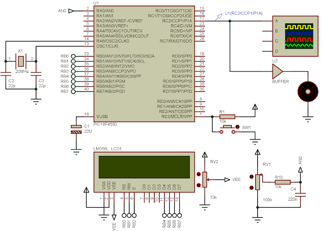
CCS PICC basic PWM example with PIC18F4550
Schematic Diagram

Click here to download this example in zip file.

Saturday, August 8, 2020

Creating A Negative Voltage Regulator Using PIC16F818 PWM

Creating A Negative Voltage Regulator Using PIC16F818 PWM

 An Overview Of Negative Voltage Creating 

A negative voltage level is useful in some situations, a negative voltage reference for ADC module, a negative supply voltage for an op-amp. 

Creating A Negative Voltage Regulator Using PIC16F818 PWM
A simulation program sample

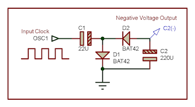
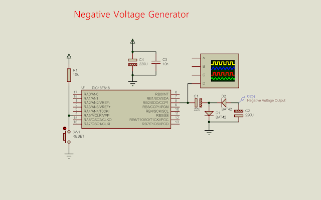
It's easily built using two high speed diodes, two polarized capacitor with an oscillator. An oscillator could be created with NE555 timer, or using an op-amp with some extra passive components.

Creating A Negative Voltage Regulator Using PIC16F818 PWM
A block of negative voltage generator. At the high cycle of OSC1, 
it charges the capacitor C1, and bypass D1 diode to the ground
creating a potential at both positive and negative pin of C1. 


Another option to create a negative voltage is using a DC-DC converter, as a case of using MC34063A. 

Using these two method as per above require an extra components placement on board. In any application where a microcontroller is needed, we can use a PWM signal created by the on-board microcontroller. Most 8-bit microcontroller, currently shipped with a PWM peripheral inside. If it isn't so, PWM signal could be created using software, by toggling an output pin with a specific period. 

PIC16F818 PWM Programming And Interfacing With CCS PICC

PIC16F818 is an 8-bit microcontroller. It's a tiny 18-pin available in DIP package. PWM signal is created by CCP1 module inside this device.

With the ease of complexity of programming, CCS PICC could configure the PWM output using a few line of code. Unlike other compiler, that a calculation to find PWM frequency and duty cycle is needed.

In CCS PICC, I use the #use pwm(options) directive to configure the module, frequency and duty cycle. But it's required to set the direction of CCP1 pin to an output direction. It's done within a few lines C code.

In this program, I use CCP1 of PIC16F818 to create PWM signal at the frequency of 1 kHz, and 50% duty cycle. This signal fed into the negative voltage generator circuit, creating a negative output voltage around -5 V, the same magnitude to the input voltage.

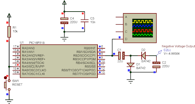
Creating A Negative Voltage Regulator Using PIC16F818 PWM
Schematic Diagram, excludes the supply voltage circuit for the MCU. CCP1 creates a PWM 
output at RB2. The MCU clock is internal 8 MHz RC oscillator inside.

C source code is just a dozen of lines.

#include<16F818.h>
#fuses INTRC_IO,NOWDT
#use delay(clock=8M)

/*Use CCP1 Module with the frequency of
1 kHz and 50% duty cycle*/
#use pwm(CCP1,FREQUENCY=1000,DUTY=50)

void main(void){
   output_B(0x00);
   set_tris_b(0x00);
   while(1){
   
   }
}

A screen shot of the running program shown below.

Creating A Negative Voltage Regulator Using PIC16F818 PWM
A simulation screen shot. Output voltage probe connects to C2(-). Output voltage 
reaches around -5 V when C2 is fully charged.

Monday, June 29, 2020

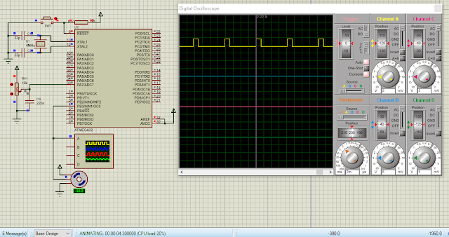
Using ADC and Timer/Counter 0 PWM of ATMega32 to rotate a DC servo motor

DC Servo Motor

A typical DC servo motor could rotate using a controlling pulse with a period of 50 Hz (20 milli seconds period). The duty cycle or high time is between 1 milli second to 2 milli seconds, with the corresponding rotating angle between -90 to +90 degree (180 degree in total).

Using ADC and Timer/Counter 0 PWM of ATMega32 to rotate a DC servo motor


Here, I use timer and counter 0 module of ATMega32 to create a PWM signal in phase correction mode. The frequency is 122 Hz regardless of the DC servo standard timing requirement. 

Using ADC and Timer/Counter 0 PWM of ATMega32 to rotate a DC servo motor
A sample of program

The clock fed to the CPU is 4 MHz. The timer/counter 0 prescaler is 1:64. The PWM frequency of phase correction mode is 4MHz/(64*510) which is 122.54 Hz. The period is 816 milli seconds.

For OCR0 step timing is (816 milli seconds)/256 is 31 micro seconds. To get a one milli second high time, OCR0 must be loaded 31. To get a two milli seconds high pulse, we must load OCR0 with 62 or 63. Hence OCR0 is varied between 31 to 63 to make the DC servo rotate at any angles.

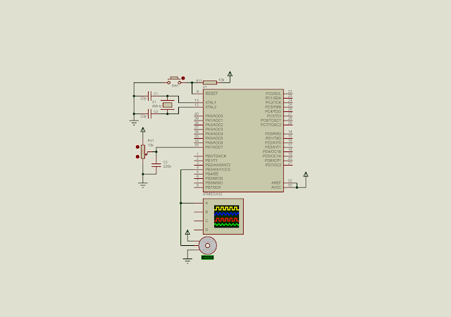
The angle is get from the analog value from a POT fed to ADC7. The 10-bit (1024) ADC value is scaled to a decimal value of 32 as referred above.

Atmel Studio 7 C Coding

The AVR C source code is implemented as below.

#include <avr/io.h>
int main(void)
{
 unsigned int adcResult,adcOld=0;
 //PA0 or ADC0 as an analog input
 DDRA=0;
 //PWM OUT
 DDRB|=(1<<3);
 /*Turn on the ADC module
 ADC Clock divided by 128
 */
 ADCSRA|=(1<<ADEN)|0x07;
 ADMUX|=0x07;
 /*Set phase correct PWM mode with non
 inverting output
 */
 TCCR0|=(1<<COM01)|(1<<WGM00)|(1<<CS01)|(1<<CS00);
 //select 1:64 pre-scaler
 //TCCR0|=(1<<CS01)|(1<<CS00);
 while (1)
 {
  //Start the conversion
  ADCSRA|=(1<<ADSC);
  //Wait for the completion
  while((ADCSRA&(1<<ADSC))==1);
  
  adcResult=ADCL+(ADCH<<8);
  if(adcResult!=adcOld)
   OCR0=((adcResult*32)/1024)+31;
  adcOld=adcResult;
 }
}

Using ADC and Timer/Counter 0 PWM of ATMega32 to rotate a DC servo motor
Schematic diagram


Click here to download its source file.

Monday, June 8, 2020

Using ADC of ATMega32 to adjust PWM duty cycle

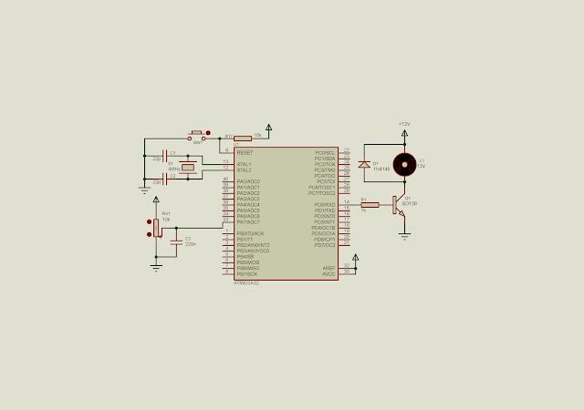
In this module we have discuss about using ADC with some typical applications. Using a POT we can adjust the analog value fed to the ADC input pin manually and linearly. With this advantage we can use the ADC value to adjust the duty cycle of PWM signal.

In this example, I use ADC to vary the PWM duty cycle between 0 to 100%. The ADC value is scaled from 1024 to 100 to fit the PWM timing. PWM signal is created by timer 0 interrupt. Each interrupt occurs for every 10 micro seconds.

Using ADC of ATMega32 to adjust PWM duty cycle

Schematic diagram

Source code:

  1. #include <avr/io.h>
  2. #include "avr/interrupt.h"
  3. unsigned char cnt=0;
  4. void speedControl(unsigned int speed){
  5. float _dutyCycle;
  6. unsigned int dutyCycle;
  7. _dutyCycle=speed*(100.0/1024);
  8. //dutyCycle=20;
  9. dutyCycle=10+(int)_dutyCycle;
  10. if(cnt<dutyCycle) PORTD|=(1<<0);
  11. if(cnt>=dutyCycle) PORTD&=~(1<<0);
  12. if(cnt>=100) cnt=0;
  13. }
  14. int main(void)
  15. { unsigned int adcResult;
  16. //PortD as output
  17. DDRD=0xFF;
  18. //PA0 or ADC0 as an analog input
  19. DDRA=0;
  20. //Set 1:8 pre-scaler
  21. TCCR0=0x02;
  22. //Clear overflow flag
  23. TIFR=0x01;
  24. //Enable Timer 0 interrupt
  25. TIMSK=0x01;
  26. //set global interrupt
  27. sei();
  28. //Turn on the ADC module
  29. ADCSRA|=(1<<ADEN);
  30. /*Select ADC7*/
  31. ADMUX|=0x07;
  32. while (1)
  33. {
  34. //Start the conversion
  35. ADCSRA|=(1<<ADSC);
  36. //Wait for the completion
  37. while((ADCSRA&(1<<ADSC))==1); //Read the result
  38. adcResult=ADCL+(ADCH<<8);
  39. speedControl(adcResult);
  40. }
  41. }
  42. ISR(TIMER0_OVF_vect){
  43. //Load -5 to make 10 uS interrupt time
  44. TCNT0=-5;
  45. cnt+=1;
  46. TIFR=0x01;
  47. }
  48.  


Click here to download its source file. Back to main tutorial page ATMega32 tutorials in C with Atmel Studio 7.

320x50

Search This Blog

Labels

25AA010A (1) 8051 (7) 93AA46B (1) ADC (30) Analog Comparator (1) Arduino (15) ARM (6) AT89C52 (7) ATMega32 (57) AVR (58) CCS PICC (28) DAC (1) DHT11 (2) Display (106) Distance Sensor (3) DS18B20 (3) dsPIC (3) dsPIC30F1010 (3) dsPIC30F2010 (1) EEPROM (5) Environment Sensor (4) esp8266 (1) I2C (29) Input/Output (68) Interrupt (19) Keil (5) Keypad (10) LCD (48) Master/Slave (1) MAX7221 (1) MCP23017 (5) MCP23S17 (4) Meter (3) MikroC (2) Motor (15) MPLABX (73) Nokia 5110 LCD (3) OLED (2) One-Wire (6) Oscillator (8) PCB (10) PCD8544 (3) PCF8574 (5) PIC (108) PIC12F (3) PIC16F628A (3) PIC16F630 (2) PIC16F716 (4) PIC16F818 (11) PIC16F818/819 (3) PIC16F84A (16) PIC16F876A (2) PIC16F877A (9) PIC16F88 (2) PIC16F887 (60) PIC18 (19) PIC18F1220 (5) PIC18F2550 (5) PIC18F4550 (12) PICKit2 (1) PWM (11) RTC (9) Sensor (11) SH1106 (1) Shift Register (11) Shift Registers (3) SPI (24) STM32 (6) STM32 Blue Pill (6) STM32CubeIDE (6) STM32F103C8T6 (6) SysTick (3) temperature sensor (11) Thermometer (21) Timer/Counter (31) TM1637 (2) UART (7) Ultrasonic (4) Voltmeter (7) WDT (1) XC16 (2) XC8 (96)

tyro-728x90