DC Servo Motor
A typical DC servo motor could rotate using a controlling pulse with a period of 50 Hz (20 milli seconds period). The duty cycle or high time is between 1 milli second to 2 milli seconds, with the corresponding rotating angle between -90 to +90 degree (180 degree in total).
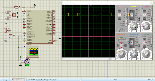
Here, I use timer and counter 0 module of ATMega32 to create a PWM signal in phase correction mode. The frequency is 122 Hz regardless of the DC servo standard timing requirement.
 |
| A sample of program |
The clock fed to the CPU is 4 MHz. The timer/counter 0 prescaler is 1:64. The PWM frequency of phase correction mode is 4MHz/(64*510) which is 122.54 Hz. The period is 816 milli seconds.
For OCR0 step timing is (816 milli seconds)/256 is 31 micro seconds. To get a one milli second high time, OCR0 must be loaded 31. To get a two milli seconds high pulse, we must load OCR0 with 62 or 63. Hence OCR0 is varied between 31 to 63 to make the DC servo rotate at any angles.
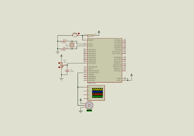
The angle is get from the analog value from a POT fed to ADC7. The 10-bit (1024) ADC value is scaled to a decimal value of 32 as referred above.
Atmel Studio 7 C Coding
The AVR C source code is implemented as below.
#include <avr/io.h>
int main(void)
{
 unsigned int adcResult,adcOld=0;
 //PA0 or ADC0 as an analog input
 DDRA=0;
 //PWM OUT
 DDRB|=(1<<3);
 /*Turn on the ADC module
 ADC Clock divided by 128
 */
 ADCSRA|=(1<<ADEN)|0x07;
 ADMUX|=0x07;
 /*Set phase correct PWM mode with non
 inverting output
 */
 TCCR0|=(1<<COM01)|(1<<WGM00)|(1<<CS01)|(1<<CS00);
 //select 1:64 pre-scaler
 //TCCR0|=(1<<CS01)|(1<<CS00);
 while (1)
 {
  //Start the conversion
  ADCSRA|=(1<<ADSC);
  //Wait for the completion
  while((ADCSRA&(1<<ADSC))==1);

  adcResult=ADCL+(ADCH<<8);
  if(adcResult!=adcOld)
   OCR0=((adcResult*32)/1024)+31;
  adcOld=adcResult;
 }
}
 |
| Schematic diagram |
Click here to download its source file.

Hello, thank you for your explanations and your code.
ReplyDeleteI have a few questions that I would appreciate if you could clarify:
1- Why did you choose 1024? Shouldn't it be 1023?
2- I would appreciate it if you could explain further about the numbers 32 and 31 and how you selected them.
3- I ran the program, and the servo motor angle is set to 180 degrees. However, it doesn't change when I adjust the potentiometer. Why is that?