Analog Comparator Module Of ATMega32 AVR
An analog module is integrated in ATMega32. It's useful for comparing two analog voltage inputs. Just like any conventional analog comparator IC, the built-in analog comparator module work in the similar way. In the case of ATMega32 there are two standard analog voltage inputs pins,- a positive input AIN0
- and a negative input AIN1.
 |
| An example of using analog comparator module |
The module compares between the potential of these two inputs. If the voltage fed to AIN0 is greater than the AIN1, it set the analog comparator output (ACO).
 |
| A simple analog comparator module without its complex logic parts. |
Actually the analog comparator module of this device is more complex than the figure listed above.
For more options, the negative input pin AIN1 could be replace with on of the ADC input pin from ADC0 to ADC7. It depends on the application we cop with.
The analog comparator module could generate interrupt on output rising, falling and toggling.
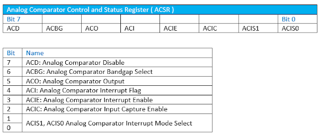
These are registers involves with the analog comparator module.
 |
| Analog Comparator Control and Status Register |
There are two more registers to select an alternative negative voltage input pin. But it's stored in the ADC module register and special IO function register (SFIOR). By default, both analog voltage input pin are AIN0 and AIN1.
I don't want to list all description of these registers because some features are not used here. For more technical details, please check the datasheet.
By default the ACD of ACSR is '0'. Hence the analog comparator module is turned on. To test the output status, we must use the ACO bit.
Programming For Analog Comparator In Atmel Studio 7
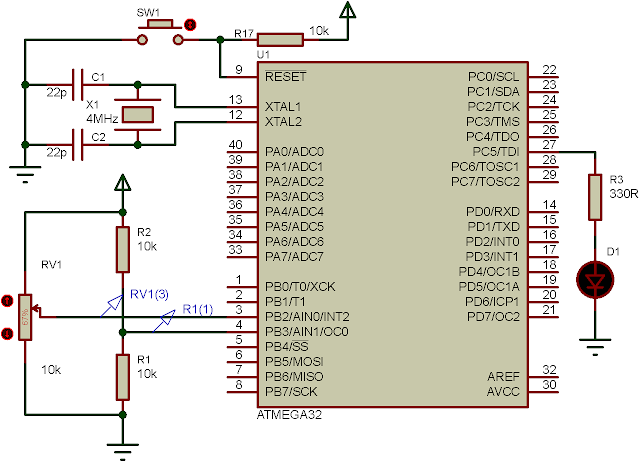
In this example, I use a simple way to compare between AIN0 and AIN1. If the analog voltage fed to AIN0 is greater than 2.5 V, the output LED connects to PC5 will set.
Atmel Studio C source code implementation is very simple.
#include <avr/io.h>
int main(void)
{
 //PC5 in output pin
 DDRC|=(1<<5);
     while (1)
    {
    /*Test the ACO bit*/
  if(ACSR&0b00100000) PORTC|=(1<<5);
  else PORTC&=~(1<<5);
      }
 |
| AIN0 varies the positive voltage while AIN1 hold a fixed voltage of 2.5 V. PC5 is set whenever AIN0 is greater than AIN1. |
Very Informative content on ACBG Thank you for the article!
ReplyDeleteHi
DeleteBSc Maths Tuition Classes in Chandigarh
ReplyDeleteBest BSc Maths Classes in Chandigarh
Top Coaching for BSc Phsyics Classes
Best BSc Physics Classes in Chandigarh
Top Coaching for BSc Chemistry Classes
Best Centre in Chandigarh for BSc Chemistry
Top Coaching for Botany Classes in Chandigarh
Online BSc Maths Tution
Best institute for BSc Maths in chandigarh
Best BSc Physics Classes in Chandigarh
Top Coaching for BSc Physics near me
Top institue for BSc Maths Online Coaching
Best Academy in Chandigarh for BSc Chemistry
Best Centre in Chandigarh for BSc Chemistry