Serial Peripheral Interface Of Atmel AVR
The serial peripheral interface (SPI) is a high speed synchronous data transfer between a microcontroller (master device) and its peripheral device (slave).In some requirements, it's use to transfer data between a microcontroller (master) and others slave microcontrollers.
 |
| The connection between a master and a slave device |
For a master data transferring, it needs three wires:
- Master Out Slave In (MOSI), a master microcontroller send data out to the slave device.
- Serial Clock (SCK), a master microcontroller outputs
synchronous clock while sending data out. - Slave Select (SS), a master microcontroller issue a low logic level to force the slave device accepting the sent data. The SS pin could be any pin on the ATMega32 microcontroller when working as a master device.
In SPI communication, one different slave device requires it own slave select pin. So the number of slave devices increase the slave select pins.
 |
| A sample of master transfer data. Clock is activated from low to high. Data is transfer at rising edge of clock. Slave select pin activate from high to low to select the slave device. |
In ATMega32, there some register to set up before the SPI is ready-to-use.
 |
| SPI Control Register - SPCR |
To use the SPI, set the SPE bit to '1' to turn on the SPI module.
The DODR is normally zero, allowing the data transfer the MSB first.
The SPI interrupt flag - SPIF uses for polling the completion of SPI transfer. It's set when the transfer is completed. The other bits are not discussed here.
Setting the MSTR bit to '1', making the ATMega32 to work in master mode.
CPOL bit is the clock polarity select bit. It's zero by default and it's low in idle mode.
The CPHA is the clock phase setting bit. By default ( 0 ), the data is sample at the leading edge of the clock.
The clock rate select if Fosc/4 when it's not set.
 |
| SPI Status Register |
The SPI interrupt flag - SPIF uses for polling the completion of SPI transfer. It's set when the transfer is completed. The other bits are not discussed here.
 |
| SPI Data Register |
Programming Example In Atmel Studio 7 C
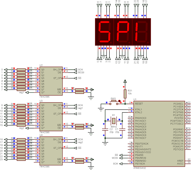
In this example I use the SPI module of ATMega32 to work in master mode. I use three slaves identical device, 74HC595 shift register. These three devices are the same in operation. So It requires only three wires. Activating the slave select pin once, these three shift register latch the data to its output register.
 |
| A sample of program, show the text "SPI" on the SSD. |
Source Code:
 |
| Schematic diagram |
We can also use the SN74HC164 serial to parallel shift registers chip to drive 7-Segment display in individual or multiplexing mode.
 |
| Simulating Program |
No comments:
Post a Comment