ATMega32 AVR Working In Slave Mode
In the previous post we introduced only the SPI master mode. In slave mode, SPI module is more easier to implement. In this example, I use one master ATMega32 to send a counting data to another slave ATMega32.
In slave mode, the ATMega32 must configured as follow:
- Set MISO pin to output
- Since it's in slave mode by default, we just enable the SPI module to make it work.
- For the data reception, we must wait until the SPIF of SPSR register is cleared.
- Finally, we just read the data buffer from the SPDR register.
 |
| At master, ATMega32 counts the input from a switch and send out the result to the slave ATMega32. At the slave side, ATMega32 just receive the data and output to the SSD. |
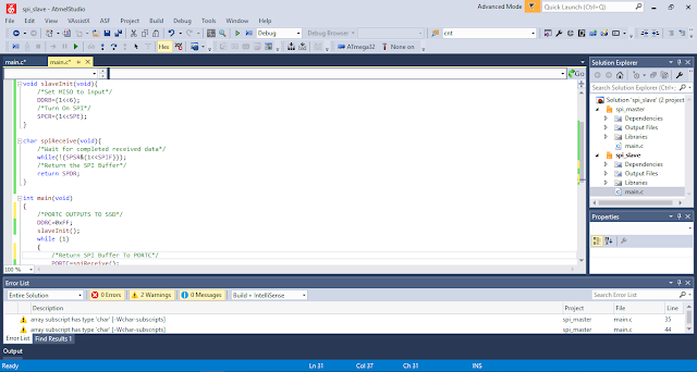
In Atmel Studio 7, I use one solution with two projects, a master project and a slave project.
 |
| SPI Master and Slave Solution |
ATMega32 Master Mode In C
For master source code in the master project:
#include <avr/io.h>
void masterInit(void){
/*Set MOSI, SCK and SS Output*/
DDRB=(1<<5)|(1<<7)|(1<<4);
/*Enable SPI Master set clock rate fck/4*/
SPCR=(1<<SPE)|(1<<MSTR);
}
void masterTransmit(char spiData){
/*Start the transmission*/
SPDR=spiData;
/*Wait for completion*/
while(!(SPSR&(1<<SPIF)));
}
int main(void)
{
unsigned char ssd[16]={0x3F,0x06,0x5B,0x4F,0x66,0x6D,0x7D,
0x07,0x7F,0x6F,0x77,0x7C,0x39,0x5E,0x79,0x71};
char cnt=0;
masterInit();
/*PIND2 inputs counting*/
DDRD&=~(1<<2);
/*TURN ON PULLUPS FOR PIND2*/
PORTD=0x04;
/*Initiate a starting transmission*/
PORTB&=~(1<<4);
masterTransmit(ssd[cnt]);
PORTB|=(1<<4);
while (1)
{
if((PIND&0x04)==0){
while((PIND&0x04)==0);
cnt+=1;
if(cnt>15) cnt=0;
PORTB&=~(1<<4);
masterTransmit(ssd[cnt]);
PORTB|=(1<<4);
}
}
}
ATMega32 Slave Mode In C
For Slave source code in the Slave project:
#include <avr/io.h>
void slaveInit(void){
/*Set MISO to input*/
DDRB=(1<<6);
/*Turn On SPI*/
SPCR=(1<<SPE);
}
char spiReceive(void){
/*Wait for completed received data*/
while(!(SPSR&(1<<SPIF)));
/*Return the SPI Buffer*/
return SPDR;
}
The full schematic is here.
 |
| Schematic Diagram |
If you want a standard PCB for ATMega32 micro-controller, you can order my AVR Microcontroller project from PCBWay with a reasonable price. Click here to get a free $5 credit for new account.
slave source code is not complete
ReplyDelete