728x90

728x90

Showing posts with label Motor. Show all posts

Wednesday, February 17, 2021

Arduino rotates a small servo motor with buttons


A servo is a kind of motor built in a module. The module contains a DC motor and a feed back control circuit. The feed back circuit regulates the motor rotating position to a specific angle receives from its master MCU, for example and Arduino.

Arduino rotates a small servo motor with buttons
Picture of this example

Controlling the position needs a specific timing. Conventionally, the signal timing frequency is 50 Hz. For more information about the servo motor timing, see this post

Servo motors are available in many physical sizes and interfaces. Choosing a servo motor depends on the application. With Arduino, there are many libraries to interface with external hardware module, including the servo motor. The Servo.h is already available after the installing of Arduino IDE. Servo control pin can be any where within the digital I/O pin and it's selected by source code writing.

To use the servo library we must #include <Servo.h>. Additionally, we must create a servo object, for example,

Servo sg90;

Using a very simple servo motor like the SG90 requires a few methods.

  1. attach() - sg90.attach(pin) : where pin is any pin on the Arduino board in use.
  2. write() - sg90.write(angle): where angle is between 0 and 190 degree.

Other sophisticated  servo motors have an angle reading line. But we don't need it here, as a simple example.

Arduino rotates a small servo motor with buttons
SG90 servo from device's specification

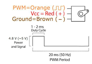
A typical servo SG90 has three lines - GND, VCC and Control. Control and VCC line requires a +5V pulse. Control line is the orange one's. It's no other than a PWM signal with low frequency.
Arduino rotates a small servo motor with buttons
SG90 pin diagram and its timing from the device's specification

In this example post, I use three tactile switches to rotate a SG90 servo motor with three corresponding angles 0 , 90 and 180 degrees respectively. I use four pin A0, A1, A2 and A3. 
Arduino rotates a small servo motor with buttons
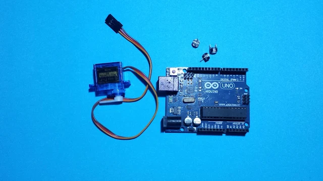
Some required parts

Arduino rotates a small servo motor with buttons
Connections Diagram

Arduino code from Github gist lists below.


Click here to download Arduino sketch.
Arduino rotates a servo motor using a potentiometer

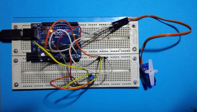
In the previous post, I use three tactile switches to rotate a servo motor to three angle positions. However, using a potentiometer, we can continuously rotates the angle of servo motor in accordance to the adjustment of the potentiometer. 

Arduino rotates a servo motor using a potentiometer
A picture of this example

With the  Arduino Servo.h and analogRead function, this task could be done easily. In this example, a potentiometer connects to pin A0 work as an analog input adjusting the angle of rotation. A servo again, connects to pin A3.

Arduino rotates a servo motor using a potentiometer
Connections Diagram

The analogRead() function return a 10-bit (1024) value from any reading from a specific analog input pin. Hence, this analog value must convert from 1024 to 180 in degree. This could be done by a simple equation as will be shown in source code.

Click here to download the sketch archive of this example.

Saturday, January 2, 2021

PIC18F4550 PWM Example in CCS PICC

Overview

Creating a varied analog voltage output from an MCU require an analog voltage generator, PWM (pulse width modulation). Making a analog voltage PWM to work, the user needs to know about all relevant register configurations to set the frequency and duty cycle of PWM signal.

However, in a high level embedded language, creating a PWM signal output doesn't need a deep level of low level hardware/register configuration. With a few C functions, the PWM signal output from any MCU could be created in a few minutes.

CCS PICC Basic Pulse Width Modulation Programming

Without using any technical detail of PWM software setting, we can create a PWM output from scratch with this compiler. In this introductory example, I use only a few C code to program the PWM.

  1. #use PWM directive
  2. pwm_set_duty_percent()
The directive #use PWM has many options, but I list a few commonly use options of this.
  • CCPx or PWMx - Select a CCP/PWM module
  • FREQUENCY=x - Set the frequency of PWM signal
  • PERIOD=x - Set the period of PWM signal
  • DUTY=x - The default duty cycle is 50% if it's not set.
For more details about this directive, check the compiler manual.

The pwm_set_duty_percent specifies the duty cycle of PWM output signal. The syntax is pwm_set_duty_percent(stream,value). Where stream is optional, and value is ranges from 0 to 1000. For example when value = 500, the PWM duty cycle is 50% and so on.

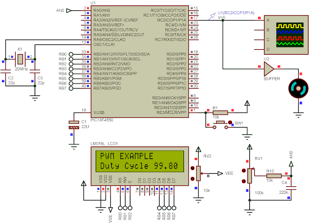
In this introductory example, I set a fixed frequency of PWM and a variable duty cycle. Duty cycle is adjusted by the variation of a POT. CCP1 is selected to make the PWM signal.

CCS PICC basic PWM example with PIC18F4550
I adjust the POT to the MAX.

C Source Code


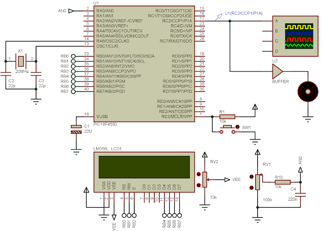
Schematic 

CCS PICC basic PWM example with PIC18F4550
Schematic Diagram

Click here to download this example in zip file.

Monday, June 29, 2020

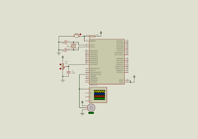
Using ADC and Timer/Counter 0 PWM of ATMega32 to rotate a DC servo motor

DC Servo Motor

A typical DC servo motor could rotate using a controlling pulse with a period of 50 Hz (20 milli seconds period). The duty cycle or high time is between 1 milli second to 2 milli seconds, with the corresponding rotating angle between -90 to +90 degree (180 degree in total).

Using ADC and Timer/Counter 0 PWM of ATMega32 to rotate a DC servo motor


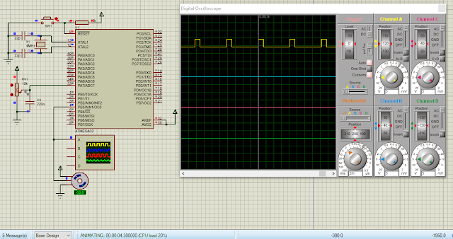
Here, I use timer and counter 0 module of ATMega32 to create a PWM signal in phase correction mode. The frequency is 122 Hz regardless of the DC servo standard timing requirement. 

Using ADC and Timer/Counter 0 PWM of ATMega32 to rotate a DC servo motor
A sample of program

The clock fed to the CPU is 4 MHz. The timer/counter 0 prescaler is 1:64. The PWM frequency of phase correction mode is 4MHz/(64*510) which is 122.54 Hz. The period is 816 milli seconds.

For OCR0 step timing is (816 milli seconds)/256 is 31 micro seconds. To get a one milli second high time, OCR0 must be loaded 31. To get a two milli seconds high pulse, we must load OCR0 with 62 or 63. Hence OCR0 is varied between 31 to 63 to make the DC servo rotate at any angles.

The angle is get from the analog value from a POT fed to ADC7. The 10-bit (1024) ADC value is scaled to a decimal value of 32 as referred above.

Atmel Studio 7 C Coding

The AVR C source code is implemented as below.

#include <avr/io.h>
int main(void)
{
 unsigned int adcResult,adcOld=0;
 //PA0 or ADC0 as an analog input
 DDRA=0;
 //PWM OUT
 DDRB|=(1<<3);
 /*Turn on the ADC module
 ADC Clock divided by 128
 */
 ADCSRA|=(1<<ADEN)|0x07;
 ADMUX|=0x07;
 /*Set phase correct PWM mode with non
 inverting output
 */
 TCCR0|=(1<<COM01)|(1<<WGM00)|(1<<CS01)|(1<<CS00);
 //select 1:64 pre-scaler
 //TCCR0|=(1<<CS01)|(1<<CS00);
 while (1)
 {
  //Start the conversion
  ADCSRA|=(1<<ADSC);
  //Wait for the completion
  while((ADCSRA&(1<<ADSC))==1);
  
  adcResult=ADCL+(ADCH<<8);
  if(adcResult!=adcOld)
   OCR0=((adcResult*32)/1024)+31;
  adcOld=adcResult;
 }
}

Using ADC and Timer/Counter 0 PWM of ATMega32 to rotate a DC servo motor
Schematic diagram


Click here to download its source file.

Sunday, May 24, 2020

Using timer 0 interrupt to create a PWM signal controlling a DC Motor

With the interrupt feature, we can create a fast PWM waveform. It produce a smother timing signal than using a pure delay function. But it is rougher than using a built-in PWM module of microcontroller.

Using timer 0 interrupt to create a PWM signal controlling a DC Motor
Schematic diagram. The CPU runs at 4 MHz. PC0 outputs a PWM signal to adjust the
speed of DC motor. PWM generated by a timer tick of timer 0 interrupt. SW3 decrease
the duty cycle of PWM. SW1 set the duty cycle to zero. SW2 increase the duty cycle,
speed up the DC motor.

In this example, I set the prescaler to 1:8. Since the CPU clock is 4 MHz, giving a 250 nano seconds period. With a 1:8 prescaler, timer 0 increase for every 8 x 250 nano seconds = 2 micro seconds.

At the timer 0 interrupt point, I want to trigger it at every 10 micro seconds. To get a 10 micro second timer tick, let (0.000010 second)/(0.000002 second) = 5. So, at the interrupt TCNT0 must be loaded with 256 - 5 = 251 or -5.

Source code's here.
#include <avr/io.h>
#include "avr/interrupt.h"
//A variable to count every 2 uS
unsigned int cnt=0;
unsigned char hTime=0;
#define speedUp (PIND&0x80)
#define stopPWM (PIND&0x40)
#define speedDw (PIND&0x20)
void myPWM(){
 if (speedUp==0)
 {
  if(hTime<95)
  hTime+=5;
  while(speedUp==0);
 }
 if (stopPWM==0)
 {
  hTime=0;
  while(stopPWM==0);
 }
  if (speedDw==0)
 {
  if(hTime>0) 
   hTime-=5;
  while(speedDw==0);
 }
 if (cnt<hTime)
 {   PORTC|=(1<<0);
 }
 else if(cnt>hTime){
  PORTC&=~(1<<0);
 }
 if(cnt>100) cnt=0;
}
int main(void)
{
 //Set PB0 to Output
 DDRC=0x01;
 //Clear PortC
 PORTC=0x00;
 //Set PD7, PD6 and PD5 to output
 DDRD=0x1F;
 //set PD7, PD6 and PD5 High
 PORTD=0xE0;
 //Set 1:8 pre-scaler
 TCCR0=0x02;
 //Clear overflow flag
 TIFR=0x01;
 //Enable Timer 0 interrupt
 TIMSK=0x01;
 //set global interrupt
 sei();
 while (1)
 {
  myPWM();
 }
}
ISR(TIMER0_OVF_vect){
 //Load -5 to make 10 uS interrupt time
 TCNT0=-5;
 cnt+=1;  TIFR=0x01;
}

I took a simulation screen shot.

Using timer 0 interrupt to create a PWM signal controlling a DC Motor
A Simulation screen shot.
PC0 create a PWM signal output with a period 1.5 milli seconds.
The PWM frequency is 666 Hz. 

Back to main tutorial page ATMega32 tutorials in C with Atmel Studio 7.


Thursday, May 21, 2020

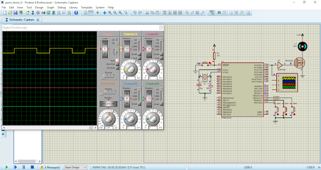
PIC16F887 controls the direction and speed of a brushed DC motor without using PWM module

A DC brushed motor commonly found some application like controlling a wheel speed of a robot, controlling the drilling speed of a numerical control machine etc.

PIC16F887 controls the direction and speed of a brushed DC motor without using PWM module
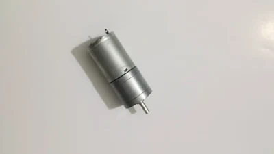
A brushed DC motor with gear box give a lower speed,
but higher torque.
The analog voltage fed into the motor directly varies the output speed of the rotating motor. The two pole of supply voltage determine the direction of rotating.

To interface with digital control device like a microcontroller, we need a proper driving circuit to protect the controller from being annoyed by the internal induction produce the the motor.

Typically, it is driven by a opto-coupler  or an L293 driver.

Without those two's, we can make our own H-Bridge driver by two complement transistors with some additional components.

In this example, I use three switches to control:
  1. motor to stop
  2. motor to rotate backward
  3. motor to rotate forward
  4. speed down
  5. and speed up
PIC16F887 controls the direction and speed of a brushed DC motor without using PWM module
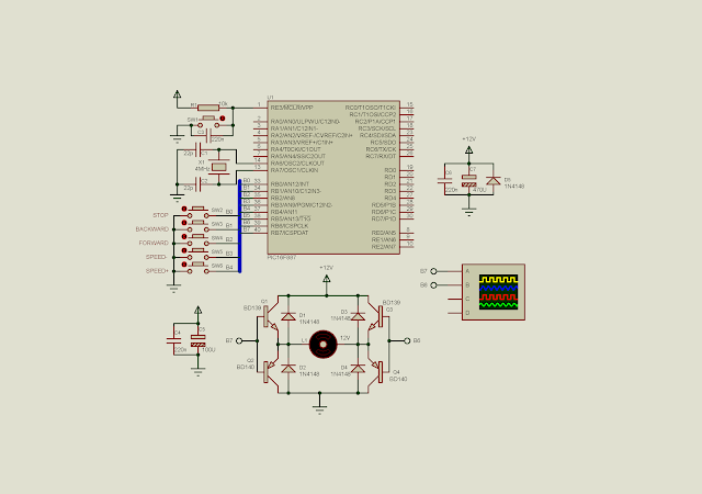
Schematic diagram
RB0 to RB4 control the direction and speed.
A DC motor is driven by an BJT H-Bridge.
The control signals to the H-Bridge is fed from
RB6 and RB7.

In the program, those five switches generate individual interrupt signal without consuming the program main loop execution time.

The XC8 program listed below:

#include<xc.h>
// PIC16F887 Configuration Bit Settings
// CONFIG1
#pragma config FOSC = XT
#pragma config WDTE = OFF
#pragma config PWRTE = OFF
#pragma config MCLRE = ON
#pragma config CP = OFF
#pragma config CPD = OFF
#pragma config BOREN = ON
#pragma config IESO = ON
#pragma config FCMEN = ON
#pragma config LVP = ON
// CONFIG2
#pragma config BOR4V = BOR40V
#pragma config WRT = OFF
#define _XTAL_FREQ 4000000
int duty=5;
/*Defualt is Stop*/
char controlReg=0;
/*Interrupt service routine*/
void interrupt _ISR(void){
    /*looking for portB interrupt
     on change by checking RBIF*/
    if(RBIF){
        /*Test individual pin*/
        /*Stop*/
        if(RB0==0)  controlReg=0;
        /*Backward*/
        if(RB1==0)  controlReg=1;
        /*Forward*/
        if(RB2==0)  controlReg=2;
        /*Decrease Speed*/
        if(RB3==0)  {
            if(duty>0)
                duty-=1;
        }
        /*Increase Speed*/
        if(RB4==0)  {
            if(duty<10)
                duty+=1;
        }
        RBIF=0;
    }
}
void main(){
    /*clear PortB*/
    PORTB=0x00;
    /*PortB0.4 inputs*/
    TRISB=0b00011111;
    /*disable all analog input of portB*/
    ANSELH=0;
    /*turn on global weak pull up*/
    nRBPU=0;
    /*Turn on all pull up resistor of portB0.4*/
    WPUB=0b00011111;
    /*enable portB interrupt on change
     for some pin pins*/
    IOCB=0b00011111;
    RBIE=1;
    /*enable global interrupt*/
    GIE=1;
    
    while(1){
        switch(controlReg){
            /*Stop the motor*/
            case 0:
                RB6=0;
                RB7=0;
                break;
            /*Forward*/
            case 1:
                RB6=0;
                RB7=1;
                for(int i=0;i<duty;i++)
                    __delay_ms(1);
                RB7=0;
                for(int i=0;i<11-duty;i++)
                    __delay_ms(1);
                break;
            /*Backward*/
            case 2:
                RB7=0;
                RB6=1;
                for(int i=0;i<duty;i++)
                    __delay_ms(1);
                RB6=0;
                for(int i=0;i<11-duty;i++)
                    __delay_ms(1);
                break;
            /*No Matched*/
            default:
                break;
        }
    }
}

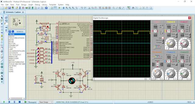
A screen shot of the simulating program.

PIC16F887 controls the direction and speed of a brushed DC motor without using PWM module
A screen shot of the simulating program.
The DC motor rotates backward.
A virtual oscilloscope shows the timing
signal fed to the H-Bridge driver.


Wednesday, May 20, 2020

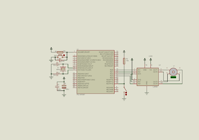
PIC16F887 interface to a bipolar stepper motor

A bipolar stepper motor commonly found in a numerical control machine, or a 3D printing machine. It gives a precise stepping angle and high torque. Its power varies with its physical size. For more information, let see this post.

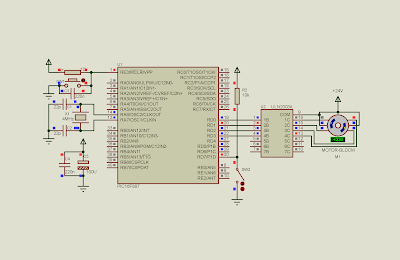
In this example, I use PIC16F887 to control the bipolar stepper motor speed and direction. The direction is determined by a switch connects to RD7.

PIC16F887 interface to a bipolar stepper motor
Schematic diagram.
Pin RD0 to RD3 drive the bipolar stepper motor.
Pin RD7 set the stepping direction.
We assume that the motor working voltage
is 24 V.

Source code is written in XC8.

#include<xc.h>

// PIC16F887 Configuration Bit Settings
// CONFIG1
#pragma config FOSC = XT
#pragma config WDTE = OFF
#pragma config PWRTE = OFF
#pragma config MCLRE = ON
#pragma config CP = OFF
#pragma config CPD = OFF
#pragma config BOREN = ON
#pragma config IESO = ON
#pragma config FCMEN = ON
#pragma config LVP = ON

// CONFIG2
#pragma config BOR4V = BOR40V
#pragma config WRT = OFF
#define _XTAL_FREQ 4000000

#define stepTime 100

//clock wise stepping
void stepCW(){
 PORTD=0b00001100;
 __delay_ms(stepTime);
 PORTD=0b00000110;
 __delay_ms(stepTime);
 PORTD=0b00000011;
 __delay_ms(stepTime);
 PORTD=0b00001001;
 __delay_ms(stepTime);
}

//counter clock wise stepping
void stepCCW(){
 PORTD=0b00001001;
 __delay_ms(stepTime);
 PORTD=0b00000011;
 __delay_ms(stepTime);
 PORTD=0b00000110;
 __delay_ms(stepTime);
 PORTD=0b00001100;
 __delay_ms(stepTime);
}

void main(){
    /*Clear PortD*/
    PORTD=0x00;
    /*RD7 input*/
    TRISD=0x80;
    while(1){
        if(RD7==0) stepCCW();
        else stepCW();
    }
}

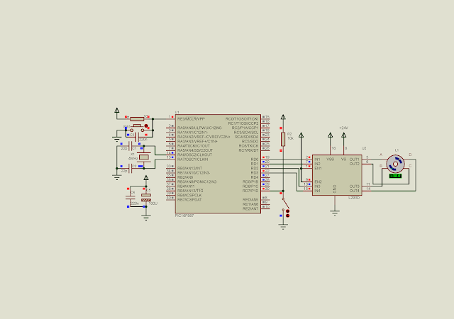
Let see the screen shot of the testing program.

PIC16F887 interface to a bipolar stepper motor
A screen shot of the simulation program.

Back to main tutorials page.

Tuesday, May 19, 2020

PIC16F887 interfaces to a unipolar stepper motor

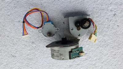
Unlike brushed DC motor, unipolar stepper could be controlled using for digital pulses. With these four digital pulses, the total rotation is difference due to the model of the stepper motor itself. It is defined by stepping angle. Some unipolar stepper motor have internal reduced gears.


Some unipolar stepper motors
Some unipolar stepper motors, removed from old photocopier and printers.

To read more about stepper motor click here.

In this example, I mention only the controlling/stepping method. There are two stepping methods, half-stepping and full-stepping.

Now, let do the half-stepping first. Half-stepping is very easy to implement. It's done by giving a high pulse one by one of the four control line consequently. Without a microcontroller, we can implement it using CD4017 fed by a digital clock source. However, half-stepping yield a lower torque force.

I use PIC16F887 to control the stepping direction of the motor. The direction is determined by a on/off switch. The stepping speed is determined by the delay between steps. More delay times makes slower rotating speed. The delay is around one hundred milliseconds.

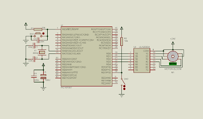
PIC16F887 interfaces to a unipolar stepper motor
The schematic diagram.
A single PortD used for both stepping and set the
direction.
RD0 to RD3 used for pulsing the four lines
of the stepper motor.
RD7 connects to a switch to get the direction
of stepping.

C source code is written using XC8.

#include"xc.h"

// CONFIG1
#pragma config FOSC = XT
#pragma config WDTE = OFF
#pragma config PWRTE = OFF
#pragma config MCLRE = ON
#pragma config CP = OFF
#pragma config CPD = OFF
#pragma config BOREN = ON
#pragma config IESO = ON
#pragma config FCMEN = ON
#pragma config LVP = ON
// CONFIG2
#pragma config BOR4V = BOR40V
#pragma config WRT = OFF

/*Parameter used for delay*/
#define _XTAL_FREQ 4000000

/*Set the step delay*/
#define stepTime 100

/*Set the button control*/
#define dirControl RD7

void stepBackward(void){
 PORTD=0x01;
 __delay_ms(stepTime);
 PORTD=0x02;
 __delay_ms(stepTime);
 PORTD=0x04;
 __delay_ms(stepTime);
 PORTD=0x08;
 __delay_ms(stepTime);
}

void stepForward(void){
 PORTD=0x08;
 __delay_ms(stepTime);
 PORTD=0x04;
 __delay_ms(stepTime);
 PORTD=0x02;
 __delay_ms(stepTime);
 PORTD=0x01;
 __delay_ms(stepTime);
}

void main(){
    //Clear PortD
    PORTD=0x80;
    //RD7 is input
    TRISD=0x80;
    while(1){
        if(dirControl) stepForward();
        else stepBackward();
    }
}

A screen shot of the simulation.

PIC16F887 interfaces to a unipolar stepper motor
A simulation screen shot of the rotation
unipolar stepper motor

For the full-stepping, it give a higher torque force with full power. If we wish to implement the full-stepping, use the code below.

#include"xc.h"

// CONFIG1
#pragma config FOSC = XT
#pragma config WDTE = OFF
#pragma config PWRTE = OFF
#pragma config MCLRE = ON
#pragma config CP = OFF
#pragma config CPD = OFF
#pragma config BOREN = ON
#pragma config IESO = ON
#pragma config FCMEN = ON
#pragma config LVP = ON
// CONFIG2
#pragma config BOR4V = BOR40V
#pragma config WRT = OFF

/*Parameter used for delay*/
#define _XTAL_FREQ 4000000

/*Set the step delay*/
#define stepTime 100

/*Set the button control*/
#define dirControl RD7

void stepForward(){
 PORTD=0b1001;
 __delay_ms(stepTime);
 PORTD=0x0011;
 __delay_ms(stepTime);
 PORTD=0b0110;
 __delay_ms(stepTime);
 PORTD=0b1100;
 __delay_ms(stepTime);
}

void stepBackward(){
 PORTD=0b1100;
 __delay_ms(stepTime);
 PORTD=0b0110;
 __delay_ms(stepTime);
 PORTD=0b0011;
 __delay_ms(stepTime);
 PORTD=0b1001;
 __delay_ms(stepTime);
}

void main(){
    //Clear PortD
    PORTD=0x80;
    //RD7 is input
    TRISD=0x80;
    while(1){
        if(dirControl) stepForward();
        else stepBackward();
    }
}

Monday, May 18, 2020

PIC16F887 controlling the DC servo motor without hardware PWM module

A servo motor is popular in any application where they need to adjust a precise rotation angle. Some servo motor could rotate at 180 degree range, while others could rotate at 360 degree.

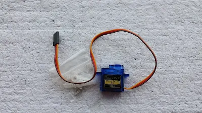
popular sg90 servo motor
A popular miniature servo motor SG90.
It runs at 5V.
The control pulse is between 4.8 V to 5V.

For more timing and angle relationship click here for more information.

In this example, PIC16F887 listens to the inputs from three buttons. They are used to control three angles of rotations, 0, 90 and 180 degrees.


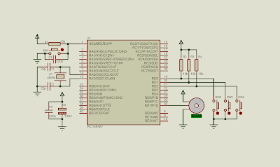
PIC16F887 servo motor control
Schematic diagram.
PIC16F887 clocks at 4 MHz with 5 V DC supply.
Three button used to rotate the servo between 0 and 180 degrees.

Source code is written in XC8.


#include"xc.h"
// CONFIG1
#pragma config FOSC = XT
#pragma config WDTE = OFF
#pragma config PWRTE = OFF
#pragma config MCLRE = ON
#pragma config CP = OFF
#pragma config CPD = OFF
#pragma config BOREN = ON
#pragma config IESO = ON
#pragma config FCMEN = ON
#pragma config LVP = ON
// CONFIG2
#pragma config BOR4V = BOR40V
#pragma config WRT = OFF
#define _XTAL_FREQ 4000000
#define sw0  RD0
#define sw90 RD1
#define sw180 RD2
void rotate0(void){
    RD7=1;
    __delay_us(1000);
    RD7=0;
    __delay_us(19000);
}
void rotate90(void){
    RD7=1;
    __delay_us(1500);
    RD7=0;
    __delay_us(18500);
}
void rotate180(void){
    RD7=1;
    __delay_us(2000);
    RD7=0;
    __delay_us(18000);
}
void main(void){
    PORTD=0x00;
    TRISD=0x07;
   
    while(1){
        if(sw0==0){
            __delay_ms(100);
            rotate0();
        }
        if(sw90==0){
            __delay_ms(100);
            rotate90();
        }
        if(sw180==0){
            __delay_ms(100);
            rotate180();
        }      
    }
}

I took a screen shot of the simulation here.

simulation screen shot
A simulation screen shot.
The picture show the rotation command of 90 degree with some
rotation angle errors.


Saturday, May 2, 2020

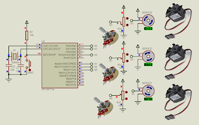
Controlling multi servo motor with PIC16F716

In the previous example, I show a simple method to rotate the angle of a servo motor using delay() function in CCS PICC.

Controlling a servo motor with PIC16F84A

In this example I use three potentiometers to adjust the three corresponding servo motor simultaneously.


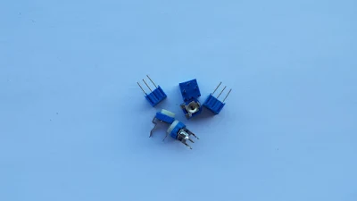
various types of Pots
A simple pot can generate variable analog voltage output,
fed to the MCU analog input.

The overall process is to convert the 8-bit analog value reading from pot to PIC16F716. Then converting the 8-bit analog data to time value in microseconds.

The 8-bit data have 256 value. This 256 value map the 1000 microsecond high time.


The PIC16F716 CPU clocks at 20 Mhz, giving a precise timing for delay() function.
Three pots connect to RA0, RA1 and RA3.
Three servo output connect to RB0, RB1 and RB2.

Source code is written in CCS PICC, and could be download here:


#include<16F716.h>
#fuses HS
#use delay(clock=20M)

void main(){
   int32 adcResult_1;
   int32 adcResult_2;
   int32 adcResult_3;
   
   int32 _h_1=0,_l_1=0;
   int32 _h_2=0,_l_2=0;
   int32 _h_3=0,_l_3=0;
   
   output_B(0x00);
   set_tris_a(0xFF);
   set_tris_b(0x00);
   setup_adc(ADC_CLOCK_INTERNAL);
   setup_adc_ports(AN0_AN1_AN3);
   
   delay_ms(2000);
   
   while(1){
   //Servo 1
      set_adc_channel(0);
      adcResult_1=read_adc();
      while(!adc_done());
      
      _h_1=1000+((1000*adcResult_1)/255);
      _l_1=20000-_h_1;
          
      output_high(pin_b0);
      delay_us(_h_1);
      output_low(pin_b0);
      delay_us(_l_1);
      
      //Servo 2
      set_adc_channel(1);
      adcResult_2=read_adc();
      while(!adc_done());
      
      _h_2=1000+((1000*adcResult_2)/255);
      _l_2=20000-_h_2;
          
      output_high(pin_b1);
      delay_us(_h_2);
      output_low(pin_b1);
      delay_us(_l_2);
      
       //Servo 3
      set_adc_channel(3);
      adcResult_3=read_adc();
      while(!adc_done());
      
      _h_3=1000+((1000*adcResult_3)/255);
      _l_3=20000-_h_3;
          
      output_high(pin_b2);
      delay_us(_h_3);
      output_low(pin_b2);
      delay_us(_l_3);
   }
}

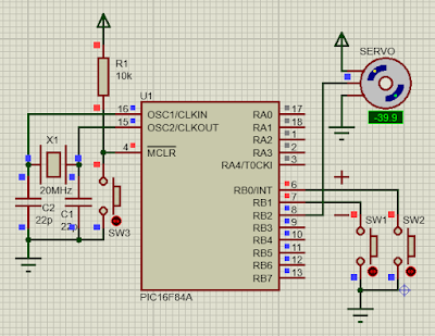
Controlling a servo motor with PIC16F84A via buttons

In the previous example, I use ATMega32 to rotate a servo motor without the hardware PWM.


SG90 mini servo motor

ATMega32 controls a servo motor with three angles rotation.

In this example, I use the popular PIC16F84A microcontroller to rotate the angle of servo motor via two button. These two buttons could rotate between -90 degree to _90 degree with about 5 degree per step.


A rotating servo motor in simulator. The PIC16F84A CPU clocks at 20MHz giving
more precise timing.

Since PIC16F84A doesn't have any hardware PWM module. I use a built-in delay function of CCS PICC compiler. Any non negative variable could make the delay.


RB0 is used to increase the rotating angle. While RB1 is used to decrease the rotating angle.

To make the servo rotate, we make a high pulse ranging from 1500 uS to 2000 us, within a 20 ms period.


source code could be download here:


#include<16F84A.h>
#fuses HS
//for delay function
#use delay(clock=20M)

void main(){
   int16 highTime=0;
   unsigned int16 _H=0,_L=0;
   output_b(0x00);
   //make RB0.1 inputs
   set_tris_b(0x03);
   //turn on port b input pullups
   port_b_pullups(true);
   
   
   while(1){
      //increase the angle
      if(input(pin_B0)==0){
         delay_ms(5);
         if(_H<2000)
         highTime+=50;
         //making high pulse
         _H=1000+(highTime/18);
         //calculate the total 20 ms period
         _L=20000-_H;
         //start the rotation
         output_high(PIN_B2);
         delay_us(_H);
         output_low(PIN_B2);
         delay_us(_L);
      }
      //decrease the angle
      if(input(pin_B1)==0){
         delay_ms(5);
         if(_H>1000)
         highTime-=50;
         //making high pulse
         _H=1000+(highTime/18); 
         //calculate the total 20 ms period
         _L=20000-_H;      
         //start the rotation
         output_high(PIN_B2);
         delay_us(_H);
         output_low(PIN_B2);
         delay_us(_L);
      }
   }
}

Wednesday, April 29, 2020

Controlling the bipolar stepper motor with ATMega32

Controlling the bi-polar stepper motor with ATMega32 Bipolar stepper motor give more precise stepping angle and higher torque. But the driving method is more difficult than the unipolar stepper motor.

Bipolar stepper motor (Model 42BYGH34-0400A)  with 1.8 degree step angle.

It is made of two distinct coils, but each coil is separated a much as possible around the rotor, to make stepping angle much smaller.


Diagram of common bipolar stepper motor.
This motor come from the Chinese company as shown in the picture above.

To make it step look at the time diagram below:

Timing Diagram for stepping clock wise and counter clock wise

Difference bipolar stepper motor has difference stepping angle. We can check its spec before use.

The example below just like the previous example. I use a switch connects to PD7 to control the stepping direction of the bipolar stepper motor.

A bipolar stepper motor connects to PORTC. PD7 is used for controlling
the direction.

Source code:

#include <avr/io.h>
#define F_CPU 16000000UL
#include "util/delay.h"
#define stepTime 100
//clock wise stepping
void stepCW(){
 PORTC=0b00001100;
 _delay_ms(stepTime);
 PORTC=0b00000110;
 _delay_ms(stepTime); 
 PORTC=0b00000011;
 _delay_ms(stepTime);
 PORTC=0b00001001;
 _delay_ms(stepTime);
}
//counter clock wise stepping
void stepCCW(){
 PORTC=0b00001001;
 _delay_ms(stepTime);
 PORTC=0b00000011;
 _delay_ms(stepTime);
 PORTC=0b00000110;
 _delay_ms(stepTime);
 PORTC=0b00001100;
 _delay_ms(stepTime);
}
int main(void)
{
    DDRC=0xFF;
 DDRD=0x7F;
 PORTD=0x80;
    while (1) 
    {
 if((PIND&0xFE)==0) stepCW();
 else stepCCW();
    }
}
Back to main tutorial page ATMega32 tutorials in C with Atmel Studio 7.

320x50

Search This Blog

Labels

25AA010A (1) 8051 (7) 93AA46B (1) ADC (30) Analog Comparator (1) Arduino (15) ARM (6) AT89C52 (7) ATMega32 (57) AVR (58) CCS PICC (28) DAC (1) DHT11 (2) Display (106) Distance Sensor (3) DS18B20 (3) dsPIC (3) dsPIC30F1010 (3) dsPIC30F2010 (1) EEPROM (5) Environment Sensor (4) esp8266 (1) I2C (29) Input/Output (68) Interrupt (19) Keil (5) Keypad (10) LCD (48) Master/Slave (1) MAX7221 (1) MCP23017 (5) MCP23S17 (4) Meter (3) MikroC (2) Motor (15) MPLABX (73) Nokia 5110 LCD (3) OLED (2) One-Wire (6) Oscillator (8) PCB (10) PCD8544 (3) PCF8574 (5) PIC (108) PIC12F (3) PIC16F628A (3) PIC16F630 (2) PIC16F716 (4) PIC16F818 (11) PIC16F818/819 (3) PIC16F84A (16) PIC16F876A (2) PIC16F877A (9) PIC16F88 (2) PIC16F887 (60) PIC18 (19) PIC18F1220 (5) PIC18F2550 (5) PIC18F4550 (12) PICKit2 (1) PWM (11) RTC (9) Sensor (11) SH1106 (1) Shift Register (11) Shift Registers (3) SPI (24) STM32 (6) STM32 Blue Pill (6) STM32CubeIDE (6) STM32F103C8T6 (6) SysTick (3) temperature sensor (11) Thermometer (21) Timer/Counter (31) TM1637 (2) UART (7) Ultrasonic (4) Voltmeter (7) WDT (1) XC16 (2) XC8 (96)

tyro-728x90