 |
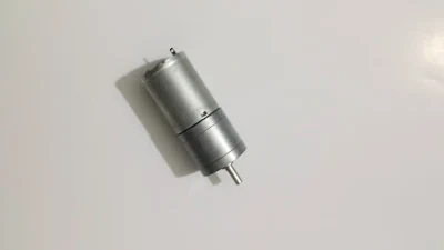
| A brushed DC motor with gear box give a lower speed, but higher torque. |
The analog voltage fed into the motor directly varies the output speed of the rotating motor. The two pole of supply voltage determine the direction of rotating.
To interface with digital control device like a microcontroller, we need a proper driving circuit to protect the controller from being annoyed by the internal induction produce the the motor.
Typically, it is driven by a opto-coupler or an L293 driver.
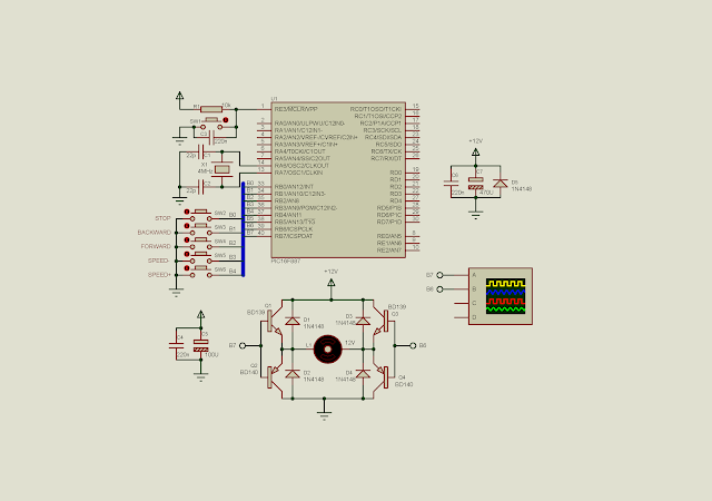
Without those two's, we can make our own H-Bridge driver by two complement transistors with some additional components.
In this example, I use three switches to control:
- motor to stop
- motor to rotate backward
- motor to rotate forward
- speed down
- and speed up
 |
| Schematic diagram RB0 to RB4 control the direction and speed. A DC motor is driven by an BJT H-Bridge. The control signals to the H-Bridge is fed from RB6 and RB7. |
In the program, those five switches generate individual interrupt signal without consuming the program main loop execution time.
The XC8 program listed below:
#include<xc.h>
// PIC16F887 Configuration Bit Settings
// CONFIG1
#pragma config FOSC = XT
#pragma config WDTE = OFF
#pragma config PWRTE = OFF
#pragma config MCLRE = ON
#pragma config CP = OFF
#pragma config CPD = OFF
#pragma config BOREN = ON
#pragma config IESO = ON
#pragma config FCMEN = ON
#pragma config LVP = ON
// CONFIG2
#pragma config BOR4V = BOR40V
#pragma config WRT = OFF
#define _XTAL_FREQ 4000000
int duty=5;
/*Defualt is Stop*/
char controlReg=0;
/*Interrupt service routine*/
void interrupt _ISR(void){
    /*looking for portB interrupt
     on change by checking RBIF*/
    if(RBIF){
        /*Test individual pin*/
        /*Stop*/
        if(RB0==0)  controlReg=0;
        /*Backward*/
        if(RB1==0)  controlReg=1;
        /*Forward*/
        if(RB2==0)  controlReg=2;
        /*Decrease Speed*/
        if(RB3==0)  {
            if(duty>0)
                duty-=1;
        }
        /*Increase Speed*/
        if(RB4==0)  {
            if(duty<10)
                duty+=1;
        }
        RBIF=0;
    }
}
void main(){
    /*clear PortB*/
    PORTB=0x00;
    /*PortB0.4 inputs*/
    TRISB=0b00011111;
    /*disable all analog input of portB*/
    ANSELH=0;
    /*turn on global weak pull up*/
    nRBPU=0;
    /*Turn on all pull up resistor of portB0.4*/
    WPUB=0b00011111;
    /*enable portB interrupt on change
     for some pin pins*/
    IOCB=0b00011111;
    RBIE=1;
    /*enable global interrupt*/
    GIE=1;

    while(1){
        switch(controlReg){
            /*Stop the motor*/
            case 0:
                RB6=0;
                RB7=0;
                break;
            /*Forward*/
            case 1:
                RB6=0;
                RB7=1;
                for(int i=0;i<duty;i++)
                    __delay_ms(1);
                RB7=0;
                for(int i=0;i<11-duty;i++)
                    __delay_ms(1);
                break;
            /*Backward*/
            case 2:
                RB7=0;
                RB6=1;
                for(int i=0;i<duty;i++)
                    __delay_ms(1);
                RB6=0;
                for(int i=0;i<11-duty;i++)
                    __delay_ms(1);
                break;
            /*No Matched*/
            default:
                break;
        }
    }
}
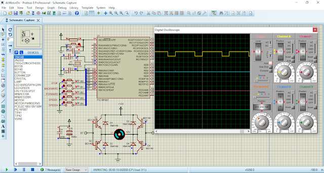
A screen shot of the simulating program.
 |
| A screen shot of the simulating program. The DC motor rotates backward. A virtual oscilloscope shows the timing signal fed to the H-Bridge driver. |
No comments:
Post a Comment