728x90

728x90

Showing posts with label PIC18F2550. Show all posts

Friday, July 18, 2025

PIC18F2550 Simple DIY Prototype Board

Overview

PIC18F2550 is a high-end 8-bit PIC micro-controller from Microchip Technology. I has a USB transceiver inside. Its Flash memory is 32kBytes and able to operates up to 48MHz (12MIPS) using its hardware PLL.

This chip is a little old but I have a dozen of of it. So I decided to make a prototype board with a PICKIT2 device programmer together since I have all required components at my workshop.

PIC18F2550 Simple DIY Prototype Board
3D View of PIC18F2550 Simple DIY Prototype Board


PIC18F2550 Simple DIY Prototype Board
3D View of PIC18F2550 Simple DIY Prototype Board

PIC18F2550 Simple DIY Prototype Board

PIC18F2550 Simple DIY Prototype Board


PIC18F2550 Simple DIY Prototype Board

PIC18F2550 Simple DIY Prototype Board 


Using a prototype board could be safer and quicker than placing and wiring all components on breadboard.


There are some functions on this board:

  1. PICKit2 device programmer
  2. +5VDC voltage regulator
  3. RS-232 to TTL converter
  4. ICSP and AVR ISP header for PIC and AVR programming
  5. DIP switch for device programming enable
  6. Four LEDs
  7. Two push buttons
  8. Reset button
  9. 28-pin male header
  10. 20MHz crystal oscillator with DIP switch


Schematic

Protues VSM has schematic capture, PCB design tool, 3D visualization, Gerber generator and view, etc. The version I use is Protues 8.9 SP3 (Build 36097). Most of components used in this PCB projects exist in this EDA software. Some footprints with 3D models needs to download from snapeda website. It's free of use but I need to register and log in to download those models. 


PIC18F2550 Simple DIY Prototype Board
Schematic Sheet #1
PIC18F2550 Simple DIY Prototype Board
Schematic Sheet #2

PIC18F2550 Simple DIY Prototype Board
Schematic Sheet #2

It contains three A4 sheets of schematics. Some identical components are used for IC sockets while other are used for IC(s).

PCB Design

PCB design tool in Protues is easy to use than other EDA tools. I make this PCB as a double-side PCB. I don't have to fabricate them by hands using a CNC machine or tone transfer method. Some PCB manufacturer could fabricate it at very low cost.

PIC18F2550 Simple DIY Prototype Board
PCB View in Protues

PCB drill holes are not accurate since it's not a Gerber view of this board. 

This PCB size is approximately 10cmx10cm which is very low cost to order from any PCB manufacturer for instance PCBWay. For single or double sided PCB of 10cmx10cm it cost only 5USD exclude shipping cost. It's a standard and high quality PCB with fast manufacturing and delivery time.

PIC18F2550 Simple DIY Prototype Board

We can order another PCB design at this size to save shipping cost.

PCBWay also offers sponsor project budget for student, electronics hobbyists for their products (PCB, PCBA, etc).

This standard PCB cost only 5USD for 5 to 10pcs (exclude shipping cost) for single or double-sided PCB. It has silk screen component legend and solder mask for both sides.

PIC18F2550 Simple DIY Prototype Board
Top Layer

PIC18F2550 Simple DIY Prototype Board
Bottom Layer

We can instantly upload the Gerber file of the PCB design and instantly quote for price. Additionally there are many shipping method for customer to choose.

If we prefer an in-house DIY PCB processing we can use the image below. Some electronics hobbyists prefer a toner transfer method which is common for most of a single sided PCB. For the double sided PCB with via we need a CNC machine to precisely drill the holes of PCB before it can be putted into an electroplating bath that connect both copper sides.
 

PIC18F2550 Simple DIY Prototype Board

PIC18F2550 Simple DIY Prototype Board

PIC18F2550 Simple DIY Prototype Board

PIC18F2550 Simple DIY Prototype Board

PIC18F2550 Simple DIY Prototype Board

Copper sides pattern making could be make using a CNC machine or a dry film process that require a chemical acid element to etch the copper clad.

Click here to download this design file. 


PCB Fabrication

I have been using PCBWay for many years now. PCBWay fabricate PCBs at low cost, fast processing time for only 24 hours, and fast delivery time using any carrier options. This double side 10cmx10cm can be fabricate at only 5USD for 5 to 10pcs by PCBWay. It's a standard PCB with silk screen and solder mask.

A DIY dsPIC30F2010 and dsPIC30F1010 Prototype Board with Programmer
10 PCBs for only 5USD
 

For different size of PCB we can instantly quote on PCBWay website using a zip PCB Gerber file without account.


A DIY dsPIC30F2010 and dsPIC30F1010 Prototype Board with Programmer
PCBWay Instant Quote
 

We can accurately see the preview of fabricated PCB generated by the company's online Gerber file viewer.

PCBWay also offer PCBA assembly service at reasonable price.

A DIY dsPIC30F2010 and dsPIC30F1010 Prototype Board with Programmer
PCBWay PCB Assembly Service


Friday, July 11, 2025

DIY PICMicro Low Pin Count DIP Prototype Board

Overview 

Using a prototype board for micro-controller firmware testing could save time and safer. Putting an on-board device programmer with prototype board could be more satisfy for electronic hobbyists.

I have some PIC18 and PIC16 series of micro-controllers left from previous projects. I don't know what to do with them anymore. So I put them on single board to PIC program testing next time I need them without checking their pin diagram, and wiring them on bread board. 

DIY PICMicro Low Pin Count DIP Prototype Board
PCB Front View

DIY PICMicro Low Pin Count DIP Prototype Board
PCB Back View
 

I designed a PCB with a 

  1. PICKit2 device programmer (with AVR ISP header)
  2. +5VDC and +3.3VDC low drop out power supply
  3.  RS-232 to TTL logic converter
  4. I2C DS1307 RTC and 24LC08 EEPROM 
  5. 4-bit LCD (HD4478)
  6. 3-digit 056'common cathode multiplexing display 
  7. One passive buzzer with transistor driver (using CCP1 PWM output pin of PIC16F876A)
  8. 8-LED that connects to PORTC of PIC16F876A
  9. A 4x4 keypad matrix that connects to PORTB of PIC16F876A
  10. Three analog inputs (one LM35 and two potentiometers) that connect to RA0...RA1 of PIC16F876A. 
  11. A 28-pin IC socket for 28-pin PIC devices
  12. A 20-pin IC socket for 20-pin PIC devices
  13. A 18-pin IC socket for 18-pin PIC devices
  14. A 14-pin IC socket for 14-pin PIC devices
  15. And a 8-pin IC socket for 8-pin PIC devices

This board seem to be a large PCB with two copper layer near a size of an A4 paper that I'm not yet fabricate it. It need a PCB fabrication service.

Schematic

I use Protues VSM Release 8.16 SP3 to design draw its circuit diagram. Some components are not in its original libraries. So I find and download some devices symbol, footprints and 3D objects from snapeda website. I separate its schematic into A4 sheets. 


DIY PICMicro Low Pin Count DIP Prototype Board
Sheet #1

DIY PICMicro Low Pin Count DIP Prototype Board
Sheet #2

DIY PICMicro Low Pin Count DIP Prototype Board
Sheet #3

DIY PICMicro Low Pin Count DIP Prototype Board
Sheet #4

DIY PICMicro Low Pin Count DIP Prototype Board
Sheet #5

This board could fit,

  1. 28-pin PIC microcontrollers: PIC16F876A, PIC16F886, etc.
  2. 20-pin PIC microcontrollers: PIC16F1459(USB), PIC16F690, etc.
  3. 18-pin PIC microcontrollers: PIC16F1827, PIC16F84A, PIC16F818, etc.
  4. 14-pin PIC microcontrollers: PIC16F630, PIC16F676, etc.
  5. 8-pin PIC microcontrollers: PIC12F629, PIC12F675, PIC12F683, etc.

These are some mid-range PIC micro-controllers I have at my own workshop.

Printed Circuit Board (PCB)

This board size is 8.02x6.30 inches that could be a little bit expensive to order from any professional PCB fabrication service. But if we need to use it with classmate or friend the share cost is cheaper.

DIY PICMicro Low Pin Count DIP Prototype Board
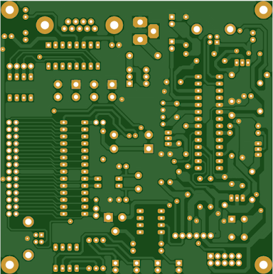
Top Copper non-mirror


DIY PICMicro Low Pin Count DIP Prototype Board
Bottom Copper


DIY PICMicro Low Pin Count DIP Prototype Board
Top Silk

I preview this PCB on an online Gerber viewer software.

DIY PICMicro Low Pin Count DIP Prototype Board
Gerber View Top Copper

DIY PICMicro Low Pin Count DIP Prototype Board
Gerber View Bottom Copper


 Click here to download its design file.


PCB Fabrication

I have been using PCBWay for many years now. PCBWay fabricate PCBs at low cost, fast processing time for only 24 hours, and fast delivery time using any carrier options. This double side 10cmx10cm can be fabricate at only 5USD for 5 to 10pcs by PCBWay. It's a standard PCB with silk screen and solder mask.

A DIY dsPIC30F2010 and dsPIC30F1010 Prototype Board with Programmer
10 PCBs for only 5USD
 

For different size of PCB we can instantly quote on PCBWay website using a zip PCB Gerber file without account.


A DIY dsPIC30F2010 and dsPIC30F1010 Prototype Board with Programmer
PCBWay Instant Quote
 

We can accurately see the preview of fabricated PCB generated by the company's online Gerber file viewer.

PCBWay also offer PCBA assembly service at reasonable price.

A DIY dsPIC30F2010 and dsPIC30F1010 Prototype Board with Programmer
PCBWay PCB Assembly Service


Saturday, May 15, 2021

PIC18F2550 interfacing with Nokia 5110 LCD

Nokia 5110 LCD module is a popular graphical LCD module for electronics hobbyists. It has a built-in LCD controller, PCD8544 48x84 pixels matrix LCD controller/driver. There are some popular modules of this graphical LCD such as, SparkFun, and Adafruit. 

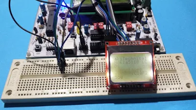
PIC18F2550 interfacing with Nokia 5110 LCD
A sample of prototyping

Serial Peripheral Interface (SPI) is communication interface between a microprocessor and this module. It is a high speed communication protocol. In this LCD module, there are only five wires relates to SPI, and other three wires for power and LED.

A popular one's from SparkFun

Hence there are 8 pins to connect to this module:

  1. VCC - Positive supply voltage (from 2.7 V to 3.3 V)
  2. GND - Ground connection
  3. SCE - Chip Select (active low)
  4. RST - Reset (active low)
  5. D/C - Data/Command mode ( low for command and high for data)
  6. DIN - SPI MOSI
  7. SCLK - SPI serial clock
  8. LED - LED backlight supplies at 3.3V maximum voltage

I will not list all its technical detail of programming here due to repetition with previous post. For programming detail, please see this post which shows the ATMega32 SPI interface to this LCD. This post show how to interface this LCD with PIC16F876A using MPLABX XC8 compiler. However it work only in software simulator without physical hardware testing.

In this post, I use my own prototyping board for PIC18F2550 to test this LCD module that I have not physically tested it before. I don't use internal SPI peripheral of PIC18F2550. The XC8 program will bit-bang the SPI via software. However using this method it will not create a high speed communication.

PIC18F2550 interfacing with Nokia 5110 LCD
Program testing on physical prototyping

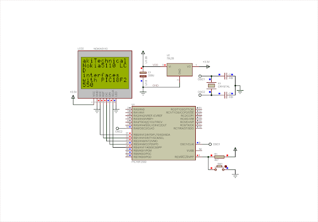
Actual schematic is shown below.

PIC18F2550 interfacing with Nokia 5110 LCD
Schematic and program simulation

I use Proteus VSM 8 to draw its schematic, and also allow the simulation of program. Supply voltage for PIC18F2550 is +5V regulated DC voltage. Pin 20 and 8 of PIC18F2550 are VDD and GND for supply voltage. They are not shown in this schematic. In physical prototyping they must be properly wired to power bus.

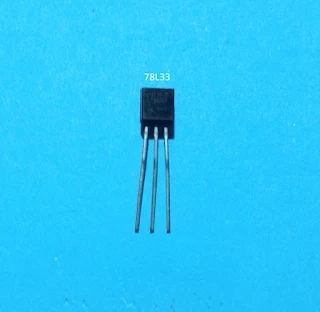
Nokia 5110 LCD module interface with PIC18F2550 using +5V TTL logic level. However it requires a +3.3V regulated DC voltage to work properly. As it's shown in the schematic above, VCC and LED pin of LCD module connects to +3.3V power pin. This voltage source regulated by 78L33 +3.3V linear voltage regulator IC in TO-92 package.

PIC18F2550 interfacing with Nokia 5110 LCD
78L33 +3.3V voltage regulator in TO-92 package

This chip is able to source up to 100mA output, suitable to drive this small LCD module. External crystal oscillator for PIC18F2550 is 20MHz in frequency without using Phase Lock Loop (PLL) of the controller.

Source code for this example program is written using XC8 v1.35 with MPLABX v1.51, which are the earlier versions for both compiler and IDE.

/*
 * PIC18F2550 interfaces to Nokia 5110
 * SPI LCD using xc8
 */

#include <xc.h>
#include "pic18f2550Config.h"
#include "fonts.h"

#define _XTAL_FREQ 20000000

#define CS      LB0
#define RST     LB1
#define D_C     LB2
#define SDO     LB3
#define SCK     LB4

#define LCD_C     0
#define LCD_D     1

#define LCD_X     84
#define LCD_Y     48

unsigned char xCount=0;

void LcdCharacter( char charactor);
void LcdClear(void);
void LcdInitialize(void);
void LcdString( char *charactor);
void LcdWrite( char dc,unsigned char _data);
void SerialOut(unsigned char dat);
void lcdNewLine();

void main() {
    LcdInitialize();
    LcdClear();
    LcdString("akiTechnical");
    LcdString("Nokia5110 LCD");
    lcdNewLine();
    LcdString("interfaces");
    lcdNewLine();
    LcdString("with PIC18F2550");


    while(1){
    }
}

void LcdCharacter( char character){
     int i;
     static int xT=0;
     LcdWrite(LCD_D,0x00);
     for(i=0;i<5;i++){
         LcdWrite(LCD_D,ASCII[character-0x20][i]);
     }
     LcdWrite(LCD_D,0x00);
     xT+=1;
     if(xT>=12){
         xT=0;
     }
     xCount=xT;
}

void LcdClear(void){
     int i;
     for(i=0;i<LCD_X*LCD_Y/8;i++) LcdWrite(LCD_D,0x00);
}

void lcdNewLine(){
    int temp;
    temp=12-xCount;
    if(temp!=0){
     for(int i=0;i<temp;i++)
         LcdCharacter(' ');
    }
}

void LcdInitialize(void){
     TRISB=0x00;
     CS=1;
     RST=0;
     RST=1;

     LcdWrite(LCD_C,0x21); // LCD Extended Commands
     LcdWrite(LCD_C,0xB1); // SET LCD CONTRAST
     LcdWrite(LCD_C,0x04); // set temp coefficient 0x04
     LcdWrite(LCD_C,0x14); // LCD bias
     LcdWrite(LCD_C,0x20);
     LcdWrite(LCD_C,0x0C); // LCD normal Mode
}

void LcdString( char *character){
     while(*character) LcdCharacter(*character++);
}

void LcdWrite( char _dc, char _data){
     D_C=_dc;
     CS=0;
     SerialOut(_data);
     CS=1;
}

void SerialOut(unsigned char dat){
    unsigned char temp;
    for(int i=0;i<8;i++){
        temp=dat;
        SCK=0;
        // TESTING MSB IF 0 SHIFT 0 OTHERWISE 1
        ((temp&0x80)==0x00)?SDO=0:SDO=1;
        SCK=1;
        dat<<=1;
    }
}

Header files for device configuration, and font file are placed in the project folder. I will not show them here. Click here to download this example program.

Tuesday, May 11, 2021

RS-232 Example using PIC18F2550

In previous post, I have show an introductory example of using RS-232 library functions in CCS PICC. Here we will try to make more programming example using this compiler on the same topic. In this programming example, the program keep received character on this data memory, until the present of keyboard ENTER key "0x0D". At this point the micro-controller will send back all received characters.


CCS PICC Program:


#include <18f2550.h>

#include <string.h>

/*use external 20MHz crystal oscillator*/ 

#fuses HS,NOWDT,PLL1,CPUDIV1

#use delay(clock=20M)

#use rs232(uart1,baud=9600)


char tmp,i=0;

char txt[20];


void main(void){


   //Clear PortC

   output_C(0x00);

   //PortC as output

   set_tris_C(0x00);

   printf("CCS PICC String Example Using PIC18F2550\n\r");

   while(1){   

   /*Test if there is character in the buffer*/

      if(kbhit()){

         tmp=getc();

         putc(tmp);

         txt[i]=tmp;

         i++;        

      }

      /*Look for the present of ENTER key*/

      if(tmp==0x0D){

         //sendText(txt);

         printf("Received Text: %s\n",txt);

         /*Clear character*/

         tmp='\0';

         /*Clear text*/

         while(i>0){

            txt[i]='\0';

            i--;

         }

      }

   }

}


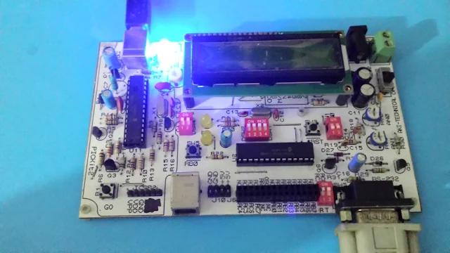
I use my own PIC18F2550 Test board to test this program getting an actual result.


RS-232 Example using PIC18F2550
Program testing on PIC18F2550 USB board

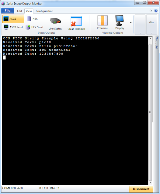
I send character via Serial Monitor tool of CCS PICC compiler. Its baud rate is 9600. COM1 is default for most desktop PC that come with RS-232 port.

RS-232 Example using PIC18F2550
Using Serial Monitor of CCS PICC compiler to send/receive ASCII character

As it's targeted PIC18F2550 this example program uses 2% of RAM, and 1% of ROM.


Sunday, April 25, 2021

PIC18f2550 RS-232 Programming example in CCS PICC

In previous post, we showed a DIY prototyping board for PIC18F2550. That board has a block of RS-232 to TTL converter but it was not tested. We will test that block here separately. 

CCS PICC has a built-in library of RS-232. It doesn't need to configure all related registers in SFR to make this module work. Its primary task is to add the #use rs232() directive in source code. This directive needs the #use delay(clock=x) directive to be declared first. For example,

#use delay (clock=4M)
#use RS232(uart1,baud=9600)

C directive showed above inform the compiler to use 4MHz clock frequency. Default UART is uart1 for most of PIC micro-controller that come with USART module inside. The baud rate is set to 9600.

UART communication for 8-bit are RC6 for transmission (Tx), and RC7 for reception (Rx). UART data I/O functions are just like the ANSI C library function. For example printf() is use for outputting ASCII data from micro-controller from its Tx pin. Other ANSI C functions are usable in CCS PICC such as getc(), putc(), kbhit(), etc.

This example will show how to use these RS-232 functions with PIC18F2550 micro-controller.

#include <18f2550.h>
//use external 20MHz crystal oscillator 
#fuses HS,NOWDT,PLL1,CPUDIV1
#use delay(clock=20M)
#use rs232(uart1,baud=9600)

void main(void){
   char temp1=0;
   //Clear PortC
   output_C(0x00);
   //PortC as output
   set_tris_C(0x00);
   printf("PIC18F2550 USB Board\n\r");
   printf("Please enter number between 0 and 3\n\r");
   printf("to toggle RC1 and RC2.\n\r");
   while(1){    
   //Test buffer
      if(kbhit()){
            temp1=getc();
            putc(temp1);
      }
      switch(temp1){
         case '0':
            output_low(pin_c1);
            temp1=0;
            printf("\tRC1 is OFF.\n\r");
            break;
         case '1':
            output_high(pin_c1);
            temp1=0;
            printf("\tRC1 is ON.\n\r");
            break;
         case '2':
            output_low(pin_c2);
            temp1=0;
            printf("\tRC2 is OFF.\n\r");
            break;
         case '3':
            output_high(pin_c2);
            temp1=0;
            printf("\tRC2 is ON.\n\r");
            break;
         case 0:
            break;
         default:
            printf("\n\rPlease enter number between 0 and 3\n\r");
            printf("to toggle RC1 and RC2.\n\r");
            temp1=0;
            break;
      }
   }
}

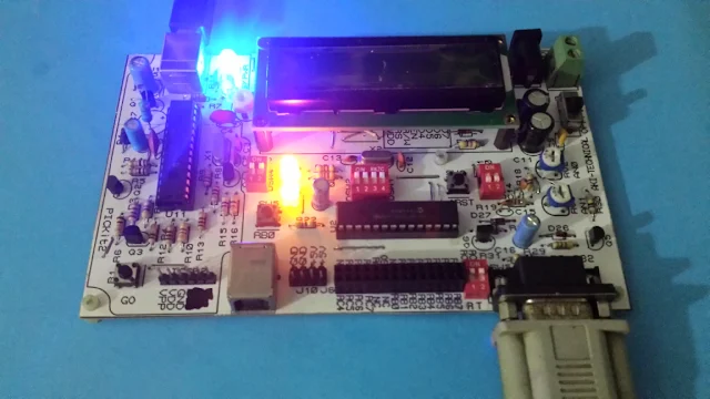
I tested this example on my prototyping board.

PIC18f2550 RS-232 Programming example in CCS PICC
Program testing on prototyping board

PIC18f2550 RS-232 Programming example in CCS PICC
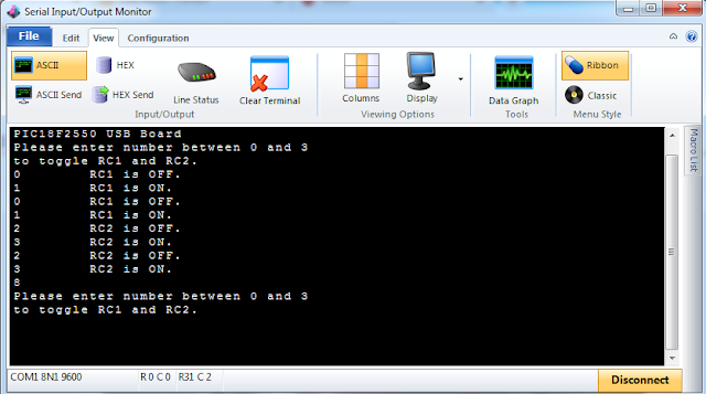
Host PC and PIC18F2550 side sending/receive data

I run this testing using a desktop PC with COM port on Windows 7 64-bit. The serial terminal showed above is a part of CCS PICC compiler IDE.

320x50

Search This Blog

Labels

25AA010A (1) 8051 (7) 93AA46B (1) ADC (30) Analog Comparator (1) Arduino (15) ARM (6) AT89C52 (7) ATMega32 (57) AVR (58) CCS PICC (28) DAC (1) DHT11 (2) Display (106) Distance Sensor (3) DS18B20 (3) dsPIC (3) dsPIC30F1010 (3) dsPIC30F2010 (1) EEPROM (5) Environment Sensor (4) esp8266 (1) I2C (29) Input/Output (68) Interrupt (19) Keil (5) Keypad (10) LCD (48) Master/Slave (1) MAX7221 (1) MCP23017 (5) MCP23S17 (4) Meter (3) MikroC (2) Motor (15) MPLABX (73) Nokia 5110 LCD (3) OLED (2) One-Wire (6) Oscillator (8) PCB (10) PCD8544 (3) PCF8574 (5) PIC (108) PIC12F (3) PIC16F628A (3) PIC16F630 (2) PIC16F716 (4) PIC16F818 (11) PIC16F818/819 (3) PIC16F84A (16) PIC16F876A (2) PIC16F877A (9) PIC16F88 (2) PIC16F887 (60) PIC18 (19) PIC18F1220 (5) PIC18F2550 (5) PIC18F4550 (12) PICKit2 (1) PWM (11) RTC (9) Sensor (11) SH1106 (1) Shift Register (11) Shift Registers (3) SPI (24) STM32 (6) STM32 Blue Pill (6) STM32CubeIDE (6) STM32F103C8T6 (6) SysTick (3) temperature sensor (11) Thermometer (21) Timer/Counter (31) TM1637 (2) UART (7) Ultrasonic (4) Voltmeter (7) WDT (1) XC16 (2) XC8 (96)

tyro-728x90