Nokia 5110 LCD module is a popular graphical LCD module for electronics hobbyists. It has a built-in LCD controller, PCD8544 48x84 pixels matrix LCD controller/driver. There are some popular modules of this graphical LCD such as, SparkFun, and Adafruit.
 |
| A sample of prototyping |
Serial Peripheral Interface (SPI) is communication interface between a microprocessor and this module. It is a high speed communication protocol. In this LCD module, there are only five wires relates to SPI, and other three wires for power and LED.
 |
| A popular one's from SparkFun |
Hence there are 8 pins to connect to this module:
- VCC - Positive supply voltage (from 2.7 V to 3.3 V)
- GND - Ground connection
- SCE - Chip Select (active low)
- RST - Reset (active low)
- D/C - Data/Command mode ( low for command and high for data)
- DIN - SPI MOSI
- SCLK - SPI serial clock
- LED - LED backlight supplies at 3.3V maximum voltage
I will not list all its technical detail of programming here due to repetition with previous post. For programming detail, please see this post which shows the ATMega32 SPI interface to this LCD. This post show how to interface this LCD with PIC16F876A using MPLABX XC8 compiler. However it work only in software simulator without physical hardware testing.
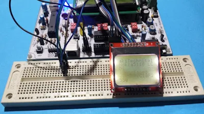
In this post, I use my own prototyping board for PIC18F2550 to test this LCD module that I have not physically tested it before. I don't use internal SPI peripheral of PIC18F2550. The XC8 program will bit-bang the SPI via software. However using this method it will not create a high speed communication.
 |
| Program testing on physical prototyping |
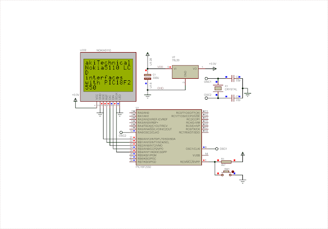
Actual schematic is shown below.
 |
| Schematic and program simulation |
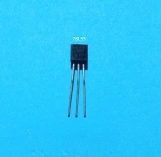
Nokia 5110 LCD module interface with PIC18F2550 using +5V TTL logic level. However it requires a +3.3V regulated DC voltage to work properly. As it's shown in the schematic above, VCC and LED pin of LCD module connects to +3.3V power pin. This voltage source regulated by 78L33 +3.3V linear voltage regulator IC in TO-92 package.
 |
| 78L33 +3.3V voltage regulator in TO-92 package |
This chip is able to source up to 100mA output, suitable to drive this small LCD module. External crystal oscillator for PIC18F2550 is 20MHz in frequency without using Phase Lock Loop (PLL) of the controller.
Source code for this example program is written using XC8 v1.35 with MPLABX v1.51, which are the earlier versions for both compiler and IDE.
Header files for device configuration, and font file are placed in the project folder. I will not show them here. Click here to download this example program.
No comments:
Post a Comment