Sunday, January 21, 2024

PIC16F887 MCP23017 LCD and Keypad Interfacing using XC8

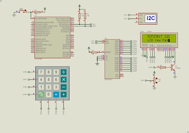
In previous post, I use the MCP23017 16-bit I/O expander chip to interface with LED and DIP switch, 4x4 matrix keypad, and the HD44780 based character LCD. Here I will put them altogether using a 4x4 matrix keypad and a 16x2 character LCD.

PIC16F887 MCP23017 LCD and Keypad Interfacing using XC8
Program Start Up


In this example, the micro-processor keep tracks of keypad scanning. When the a key-press is detected it will send to a 16x2 character LCD via the MCP23017 I2C communication interface. The LCD is automatically create new line and return home by software.

  1. /*
  2.  * File: main.c
  3.  * Author: Admin
  4.  *
  5.  * Created on January 22, 2024, 9:04 AM
  6.  */
  7.  
  8. #include <xc.h>
  9. #include "config.h"
  10. #include "mcp23017.h"
  11.  
  12. #define _XTAL_FREQ 8000000
  13.  
  14. void main(void) {
  15. OSCCONbits.IRCF=7;
  16. __delay_ms(100);
  17. lcd_init();
  18. __delay_ms(100);
  19. lcd_text(" MCP23017 I2C");
  20. lcd_xy(1,2);
  21. lcd_text(" LCD Key Pad");
  22. __delay_ms(3000);
  23. lcd_clear();
  24. uint8_t temp,counter=0,new_line=0,line_num=1;
  25. while(1){
  26. temp=keyScan();
  27. if(temp!=0xFF){
  28. lcd_data(temp);
  29. counter++;
  30. __delay_ms(250);
  31. }
  32. if(counter>=16) {counter=0; new_line=1;}
  33. if(new_line){
  34. new_line=0;
  35. line_num++;
  36. if(line_num==2) lcd_xy(1,2);
  37. if(line_num==3){lcd_clear(); line_num=1;}
  38. }
  39. }
  40. return;
  41. }
  42.  

The PIC16F887 use the I2C clock frequency of 400kHz without disruption. Program simulation in Proteus doesn't run smoothly. So I need to test this firmware on a prototype board next.

PIC16F887 MCP23017 LCD and Keypad Interfacing using XC8
Keypad Scanning and LCD Display Tasks

Click here to download this example package from GitHub.


PIC16F887 MCP23017 I2C LCD Example using XC8

In previous post, I showed a simple keypad scanning and 7-Segment display example using the MCP23017 16-bit I/O expander chip. However we can use a single 8-bit port of this chip to control a HD44780 based character LCD in 4-bit data transfer mode.

PIC16F887 MCP23017 I2C LCD Example using XC8
Simulating Program in Proteus


In this example, I use GPIOA of the MCP23017 to control a 16x2 character LCD via its 4-bit data bus. However LCD command and data still in 8-bit. The 8-bit data is divided into two nibbles. The higher nibble is transferred and latched into the LCD first. Then the lower nibble is transferred and latched into the LCD to complete the command or data transmission.

  1. /*
  2.  * File: main.c
  3.  * Author: Admin
  4.  *
  5.  * Created on January 21, 2024, 8:18 PM
  6.  */
  7.  
  8. #include <stdio.h>
  9. #include <xc.h>
  10. #include "config.h"
  11. #include "mcp23017.h"
  12.  
  13. #define _XTAL_FREQ 8000000UL
  14.  
  15. const char RS=0,RW=1,EN=2;
  16. __bit BLK_ON=0;
  17.  
  18. void lcd_command(uint8_t temp){
  19. uint8_t command,led;
  20. command=temp&0xF0;
  21. if(BLK_ON==1) led=0x08;
  22. else led=0;
  23. mcp23017_write(OLATA,command|led|(1<<EN));
  24. __delay_us(10);
  25. mcp23017_write(OLATA,command|led);
  26. __delay_us(25);
  27.  
  28. command=temp<<4;
  29. mcp23017_write(OLATA,command|led|(1<<EN));
  30. __delay_us(10);
  31. mcp23017_write(OLATA,command|led);
  32. __delay_us(25);
  33. }
  34.  
  35. void lcd_data(uint8_t temp){
  36. uint8_t data,led;
  37. data=temp&0xF0;
  38. if(BLK_ON==1) led=0x08;
  39. else led=0;
  40. mcp23017_write(OLATA,data|led|(1<<EN)|(1<<RS));
  41. __delay_us(10);
  42. mcp23017_write(OLATA,data|led|(1<<RS));
  43. __delay_us(25);
  44.  
  45. data=temp<<4;
  46. mcp23017_write(OLATA,data|led|(1<<EN)|(1<<RS));
  47. __delay_us(10);
  48. mcp23017_write(OLATA,data|led|(1<<RS));
  49. __delay_us(25);
  50. }
  51.  
  52. void lcd_xy(uint8_t x, uint8_t y){
  53. uint8_t cursor[]={0x80,0xC0};
  54. lcd_command(cursor[y-1]+x-1);
  55. }
  56.  
  57. void lcd_text(uint8_t *text){
  58. while(*text) lcd_data(*text++);
  59. }
  60.  
  61. void lcd_clear(void){
  62. lcd_command(0x01);
  63. __delay_ms(5);
  64. }
  65.  
  66. void lcd_init(void){
  67. BLK_ON=1;
  68. mcp23017_init();
  69. lcd_command(0x33);
  70. __delay_us(10);
  71. lcd_command(0x32);
  72. __delay_us(10);
  73. lcd_command(0x28);
  74. __delay_us(10);
  75. lcd_command(0x0F);
  76. __delay_us(10);
  77. lcd_command(0x01);
  78. __delay_ms(5);
  79. lcd_command(0x06);
  80. __delay_us(10);
  81. }
  82.  
  83. void main(void) {
  84. __delay_ms(100);
  85. OSCCONbits.IRCF=7;
  86. lcd_init();
  87. __delay_us(100);
  88. lcd_text(" PIC16F887 I2C");
  89. lcd_xy(1,2);
  90. lcd_text("And MCP23017 LCD");
  91. __delay_ms(2500);
  92. lcd_clear();
  93. lcd_command(0x0C);
  94. lcd_text("Counter Variable");
  95. long counter=0;
  96. uint8_t msg[10];
  97. while(1){
  98. sprintf(msg,"%ld",counter);
  99. lcd_xy(1,2); lcd_text(msg);
  100. counter++;
  101. __delay_us(250);
  102. }
  103. return;
  104. }
  105.  

The I2C master microprocessor send a counter variable to the LCD for every 250 Milli seconds. Simulating program in Proteus has interrupt due to firmware issue. So we can try on a real circuit.

PIC16F887 MCP23017 I2C LCD Example using XC8
Simulating Program in Proteus

The micro-controller use its internal 8MHz RC oscillator. So I left the CLKOUT and CLKIN pins unconnected. These two pin could be used for general purpose I/O.

Click here to download this example.

PIC16F887 MCP23017 Key Pad and 7-Segment Display Example using XC8

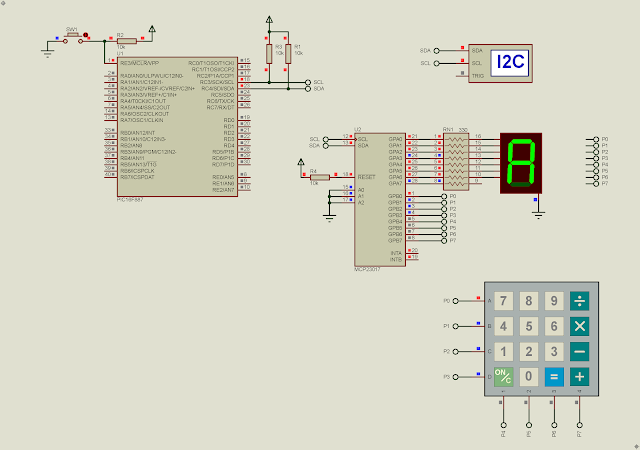
In previous post, I introduce about using the MCP23017 16-bit I2C I/O expander with PIC16F887. This chip can be interfaced with various types of I/O device. In this example, I a PIC16F887 micro-controller command this I2C chip to scan and find key-press from a 4x4 matrix keypad. Key present will show on a single common cathode seven-segment display.

PIC16F887 MCP23017 Key Pad and 7-Segment Display Example using XC8
Simulating Program in Proteus


The I2C operates at 400kHz serial clock frequency. Lower nibber of GPB is configured as digital output while the higher nibble is configured as digital input detecting key-press. GPA is configured as digital output, driving a 7-Segment display.

PIC16F887 MCP23017 Key Pad and 7-Segment Display Example using XC8
Two 4x4 matrix keypad for Arduino

  1. /*
  2.  * File: main.c
  3.  * Author: Admin
  4.  *
  5.  * Created on January 21, 2024, 7:12 PM
  6.  */
  7.  
  8. #include <xc.h>
  9. #include "config.h"
  10. #include "mcp23017.h"
  11.  
  12. const uint8_t d_7[]={0x3F,0x06,0x5B,0x4F,
  13. 0x66,0x6D,0x7D,0x07,
  14. 0x7F,0x6F,0x77,0x7C,
  15. 0x39,0x5E,0x79,0x71};
  16. const uint8_t key_16[][4]={7,8,9,15,
  17. 4,5,6,14,
  18. 1,2,3,13,
  19. 10,0,11,12};
  20.  
  21. uint8_t keyScan(void){
  22. uint8_t data,temp;
  23. for(uint8_t i=0;i<4;i++){
  24. data=1<<i;
  25. mcp23017_write(OLATB,data);
  26. __delay_ms(10);
  27. data=mcp23017_read(GPIOB);
  28. data>>=4;
  29. if(data==0x01) {temp=key_16[i][0]; break;}
  30. else if(data==0x02) {temp=key_16[i][1]; break;}
  31. else if(data==0x04) {temp=key_16[i][2]; break;}
  32. else if(data==0x08) {temp=key_16[i][3]; break;}
  33. else temp=0xFF;
  34. __delay_ms(10);
  35. }
  36. return temp;
  37. }
  38. void main(void) {
  39. OSCCONbits.IRCF=7;
  40. __delay_ms(100);
  41. mcp23017_init();
  42. uint8_t temp=0xFF;
  43. while(1){
  44. temp=keyScan();
  45. if(temp!=0xFF){
  46. mcp23017_write(OLATA,d_7[temp]);
  47. __delay_ms(100);
  48. }
  49. }
  50. return;
  51. }
  52.  

When key-press is found the micro-controller sends a seven-segment data to GPA of the MCP23017, and it will wait for 100 Milli seconds. A key value of 0xFF is ignored.

Click here to download this example. If you prefer another I2C device, you can choose the PCF8574AP that's described in this post.

PIC16F887 MCP23017 I2C GPIO Example using XC8

Overview

The MCP23017 is a 16-bit I2C I/O expander chip. It could be used for digital input reading/writing, relay driving, multiplexing display driving, keypad scanning, LCD controlling, etc. It uses a Two-Wire serial interface or I2C with two communication line, serial data (SDA) and serial clock (SCL).

PIC16F887 MCP23017 I2C GPIO Example using XC8
Simulating Program for I/O Reading and Writing

This chip has more functionalities compare to the older PCF8574 I/O expander. It has data direction control, pull-up resistor control, input output register, output latch register, interrupt control and status registers, etc. For an introductory example, you can see this post that I use the ATMega32 micro-controller.

PIC16F887 MCP23017 I2C GPIO Example using XC8
The MCP23017 DIP-28 I Posses


This chip comes with various packages. A DIP-28 is preferred for most of electronics hobby projects.

PIC16F887 MCP23017 I2C GPIO Example using XC8
MCP23017 Package Types
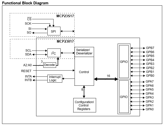
The MCP23S17 implements the Serial Peripheral Interface (SPI) communication interface. The MCP23017 has,

  • I2C communication interface 
  • reset (active high)
  • additional address setting
  • interrupts output
  • two 8-bit bi-directional GPIO, GPA and GPB.
PIC16F887 MCP23017 I2C GPIO Example using XC8
Functional Block Diagram


This chip able to operate at high speed up to 1.7MHz. Its operating voltage ranges from 1.8V to 5.5V. For electronics hobbyist prototyping a 5V stable supply voltage is common.
PIC16F887 MCP23017 I2C GPIO Example using XC8
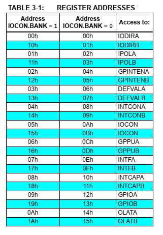
Register Addresses
All registers listed above are configuration registers, status registers, and data registers. It has two memory banks, bank0 and bank1. By default we work with bank0. For example,

  • IODIRA - I/O Direction Register A (0 for output and 1 for input)
  • IODIRB - I/O Direction Register B (0 for output and 1 for input)
  • GPPUA - GPIO Pull-Up Resistor Register A (1 for enable and 0 for disable)
  • GPPUB - GPIO Pull-Up Resistor Register B (1 for enable and 0 for disable)
  • GPIOA - General Purpose I/O Port Register A ( this register is for reading data from PORTA)
  • GPIOB - General Purpose I/O Port Register B ( this register is for reading data from PORTB)
  • OLATA - Output Latch Register A ( this register is for writing data to output PORTA) 
  • OLATB - Output Latch Register B ( this register is for writing data to output PORTB)

For more detail you can see its datasheet

To write to this chip the controller needs to write its slave address of 0x40 (A2...A0 are logic 0) followed by its register address and data. It also have sequential addressing mode but I don't mention it here.

To read from this chip the controller needs to write its slave address 0x40 (A2...A0 are logic 0) followed by its register address. Then start a new write session of the device slave address of 0x41 followed the I2C read mode to get the data.

MPLABX IDE and XC8 Programming 

This introductory example, the master micro-processor just send a LED shifting data to the I2C slave MCP23017 chip. I use the I2C communication module of PIC16F887. Its serial clock frequency is 400kHz.

  1. /*
  2.  * File: main.c
  3.  * Author: Admin
  4.  *
  5.  * Created on January 21, 2024, 3:07 PM
  6.  */
  7.  
  8. #include <xc.h>
  9. #include "config.h"
  10. #include "i2c.h"
  11.  
  12. #define _XTAL_FREQ 8000000UL
  13.  
  14. #define MCP23017_W 0x40
  15. #define MCP23017_R 0x41
  16.  
  17. void mcp23017_write(uint8_t address, uint8_t data){
  18. i2c_start();
  19. i2c_write(MCP23017_W);
  20. i2c_write(address);
  21. i2c_write(data);
  22. i2c_stop();
  23. }
  24.  
  25. void main(void) {
  26. OSCCONbits.IRCF=7;
  27. i2c_init(400000);
  28. mcp23017_write(0,0);
  29. while(1){
  30. uint8_t i=0;
  31. while(i<8){
  32. mcp23017_write(0x14,1<<i);
  33. i++;
  34. __delay_ms(100);
  35. }
  36. }
  37. return;
  38. }
  39.  

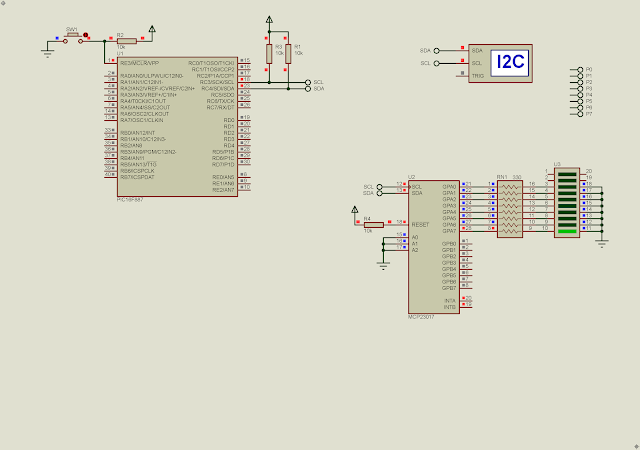
I use only GPA for LED output. The LED shifts for every 100 Milli seconds.
PIC16F887 MCP23017 I2C GPIO Example using XC8
Proteus Simulation
I simulate this program using Proteus VSM 8. Click here to download this example.


The following example, the MCP23017 is used for reading data from GPB and writing data back to GPA.

  1. /*
  2.  * File: main.c
  3.  * Author: Admin
  4.  *
  5.  * Created on January 21, 2024, 4:16 PM
  6.  */
  7.  
  8. #include <xc.h>
  9. #include "config.h"
  10. #include "i2c.h"
  11.  
  12. #define _XTAL_FREQ 8000000UL
  13.  
  14. #define MCP23017_W 0x40
  15. #define MCP23017_R 0x41
  16.  
  17. #define IODIRA 0x00
  18. #define IODIRB 0x01
  19. #define GPPUB 0x0D
  20. #define GPIOB 0x13
  21. #define OLATA 0x14
  22.  
  23. void mcp23017_write(uint8_t address, uint8_t data){
  24. i2c_start();
  25. i2c_write(MCP23017_W);
  26. i2c_write(address);
  27. i2c_write(data);
  28. i2c_stop();
  29. }
  30.  
  31. uint8_t mcp23017_read(uint8_t address){
  32. uint8_t data;
  33. i2c_start();
  34. i2c_write(MCP23017_W);
  35. i2c_write(address);
  36. i2c_stop();
  37.  
  38. i2c_start();
  39. i2c_write(MCP23017_R);
  40. data=i2c_read(0);
  41. i2c_stop();
  42. return data;
  43. }
  44.  
  45. void main(void) {
  46. OSCCONbits.IRCF=7;
  47. i2c_init(400000);
  48. mcp23017_write(IODIRA,0); //GPA AS OUTPUT
  49. mcp23017_write(IODIRB,0xFF); //GPB AS INPUT
  50. mcp23017_write(GPPUB,0xFF); //GPB PULL-UP ENABLE
  51. while(1){
  52. //READ GPB INPUT DATA
  53. uint8_t temp=mcp23017_read(GPIOB);
  54. __delay_ms(10);
  55. //WRITE GPA OUTPUT DATA
  56. mcp23017_write(OLATA,temp);
  57. __delay_ms(50);
  58. }
  59. return;
  60. }
  61.  

I enable its pull-up resistor at GPB without adding additional resistor the the circuit.

PIC16F887 MCP23017 I2C GPIO Example using XC8
Schematic Diagram

Simulating program in Proteus work very well. Click here to download this example.


Search This Blog

Labels

25AA010A (1) 8051 (7) 93AA46B (1) ADC (30) Analog Comparator (1) Arduino (15) ARM (6) AT89C52 (7) ATMega32 (54) AVR (57) CCS PICC (28) DAC (1) DHT11 (2) Display (105) Distance Sensor (3) DS18B20 (3) dsPIC (2) dsPIC30F1010 (2) EEPROM (5) Environment Sensor (4) esp8266 (1) I2C (29) Input/Output (67) Interrupt (19) Keil (5) Keypad (10) LCD (46) Master/Slave (1) MAX7221 (1) MCP23017 (5) MCP23S17 (4) Meter (3) MikroC (2) Motor (15) MPLABX (66) Nokia 5110 LCD (3) OLED (2) One-Wire (6) Oscillator (8) PCB (6) PCD8544 (3) PCF8574 (5) PIC (107) PIC12F (2) PIC16F628A (2) PIC16F630 (1) PIC16F716 (3) PIC16F818 (10) PIC16F818/819 (2) PIC16F84A (15) PIC16F876A (1) PIC16F877A (9) PIC16F88 (1) PIC16F887 (60) PIC18 (19) PIC18F1220 (4) PIC18F2550 (3) PIC18F4550 (12) PWM (11) RTC (8) Sensor (10) SH1106 (1) Shift Register (11) Shift Registers (2) SPI (24) STM32 (6) STM32 Blue Pill (6) STM32CubeIDE (6) STM32F103C8T6 (6) SysTick (3) temperature sensor (11) Thermometer (21) Timer/Counter (30) TM1637 (2) UART (7) Ultrasonic (4) Voltmeter (7) WDT (1) XC16 (2) XC8 (94)