728x90

728x90

Showing posts with label Input/Output. Show all posts

Friday, July 11, 2025

DIY PICMicro Low Pin Count DIP Prototype Board

Overview 

Using a prototype board for micro-controller firmware testing could save time and safer. Putting an on-board device programmer with prototype board could be more satisfy for electronic hobbyists.

I have some PIC18 and PIC16 series of micro-controllers left from previous projects. I don't know what to do with them anymore. So I put them on single board to PIC program testing next time I need them without checking their pin diagram, and wiring them on bread board. 

DIY PICMicro Low Pin Count DIP Prototype Board
PCB Front View

DIY PICMicro Low Pin Count DIP Prototype Board
PCB Back View
 

I designed a PCB with a 

  1. PICKit2 device programmer (with AVR ISP header)
  2. +5VDC and +3.3VDC low drop out power supply
  3.  RS-232 to TTL logic converter
  4. I2C DS1307 RTC and 24LC08 EEPROM 
  5. 4-bit LCD (HD4478)
  6. 3-digit 056'common cathode multiplexing display 
  7. One passive buzzer with transistor driver (using CCP1 PWM output pin of PIC16F876A)
  8. 8-LED that connects to PORTC of PIC16F876A
  9. A 4x4 keypad matrix that connects to PORTB of PIC16F876A
  10. Three analog inputs (one LM35 and two potentiometers) that connect to RA0...RA1 of PIC16F876A. 
  11. A 28-pin IC socket for 28-pin PIC devices
  12. A 20-pin IC socket for 20-pin PIC devices
  13. A 18-pin IC socket for 18-pin PIC devices
  14. A 14-pin IC socket for 14-pin PIC devices
  15. And a 8-pin IC socket for 8-pin PIC devices

This board seem to be a large PCB with two copper layer near a size of an A4 paper that I'm not yet fabricate it. It need a PCB fabrication service.

Schematic

I use Protues VSM Release 8.16 SP3 to design draw its circuit diagram. Some components are not in its original libraries. So I find and download some devices symbol, footprints and 3D objects from snapeda website. I separate its schematic into A4 sheets. 


DIY PICMicro Low Pin Count DIP Prototype Board
Sheet #1

DIY PICMicro Low Pin Count DIP Prototype Board
Sheet #2

DIY PICMicro Low Pin Count DIP Prototype Board
Sheet #3

DIY PICMicro Low Pin Count DIP Prototype Board
Sheet #4

DIY PICMicro Low Pin Count DIP Prototype Board
Sheet #5

This board could fit,

  1. 28-pin PIC microcontrollers: PIC16F876A, PIC16F886, etc.
  2. 20-pin PIC microcontrollers: PIC16F1459(USB), PIC16F690, etc.
  3. 18-pin PIC microcontrollers: PIC16F1827, PIC16F84A, PIC16F818, etc.
  4. 14-pin PIC microcontrollers: PIC16F630, PIC16F676, etc.
  5. 8-pin PIC microcontrollers: PIC12F629, PIC12F675, PIC12F683, etc.

These are some mid-range PIC micro-controllers I have at my own workshop.

Printed Circuit Board (PCB)

This board size is 8.02x6.30 inches that could be a little bit expensive to order from any professional PCB fabrication service. But if we need to use it with classmate or friend the share cost is cheaper.

DIY PICMicro Low Pin Count DIP Prototype Board
Top Copper non-mirror


DIY PICMicro Low Pin Count DIP Prototype Board
Bottom Copper


DIY PICMicro Low Pin Count DIP Prototype Board
Top Silk

I preview this PCB on an online Gerber viewer software.

DIY PICMicro Low Pin Count DIP Prototype Board
Gerber View Top Copper

DIY PICMicro Low Pin Count DIP Prototype Board
Gerber View Bottom Copper


 Click here to download its design file.


PCB Fabrication

I have been using PCBWay for many years now. PCBWay fabricate PCBs at low cost, fast processing time for only 24 hours, and fast delivery time using any carrier options. This double side 10cmx10cm can be fabricate at only 5USD for 5 to 10pcs by PCBWay. It's a standard PCB with silk screen and solder mask.

A DIY dsPIC30F2010 and dsPIC30F1010 Prototype Board with Programmer
10 PCBs for only 5USD
 

For different size of PCB we can instantly quote on PCBWay website using a zip PCB Gerber file without account.


A DIY dsPIC30F2010 and dsPIC30F1010 Prototype Board with Programmer
PCBWay Instant Quote
 

We can accurately see the preview of fabricated PCB generated by the company's online Gerber file viewer.

PCBWay also offer PCBA assembly service at reasonable price.

A DIY dsPIC30F2010 and dsPIC30F1010 Prototype Board with Programmer
PCBWay PCB Assembly Service


Sunday, January 21, 2024

PIC16F887 MCP23017 Key Pad and 7-Segment Display Example using XC8

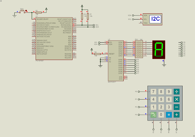
In previous post, I introduce about using the MCP23017 16-bit I2C I/O expander with PIC16F887. This chip can be interfaced with various types of I/O device. In this example, I a PIC16F887 micro-controller command this I2C chip to scan and find key-press from a 4x4 matrix keypad. Key present will show on a single common cathode seven-segment display.

PIC16F887 MCP23017 Key Pad and 7-Segment Display Example using XC8
Simulating Program in Proteus

The I2C operates at 400kHz serial clock frequency. Lower nibber of GPB is configured as digital output while the higher nibble is configured as digital input detecting key-press. GPA is configured as digital output, driving a 7-Segment display.

PIC16F887 MCP23017 Key Pad and 7-Segment Display Example using XC8
Two 4x4 matrix keypad for Arduino

  1. /*
  2.  * File: main.c
  3.  * Author: Admin
  4.  *
  5.  * Created on January 21, 2024, 7:12 PM
  6.  */
  7.  
  8. #include <xc.h>
  9. #include "config.h"
  10. #include "mcp23017.h"
  11.  
  12. const uint8_t d_7[]={0x3F,0x06,0x5B,0x4F,
  13. 0x66,0x6D,0x7D,0x07,
  14. 0x7F,0x6F,0x77,0x7C,
  15. 0x39,0x5E,0x79,0x71};
  16. const uint8_t key_16[][4]={7,8,9,15,
  17. 4,5,6,14,
  18. 1,2,3,13,
  19. 10,0,11,12};
  20.  
  21. uint8_t keyScan(void){
  22. uint8_t data,temp;
  23. for(uint8_t i=0;i<4;i++){
  24. data=1<<i;
  25. mcp23017_write(OLATB,data);
  26. __delay_ms(10);
  27. data=mcp23017_read(GPIOB);
  28. data>>=4;
  29. if(data==0x01) {temp=key_16[i][0]; break;}
  30. else if(data==0x02) {temp=key_16[i][1]; break;}
  31. else if(data==0x04) {temp=key_16[i][2]; break;}
  32. else if(data==0x08) {temp=key_16[i][3]; break;}
  33. else temp=0xFF;
  34. __delay_ms(10);
  35. }
  36. return temp;
  37. }
  38. void main(void) {
  39. OSCCONbits.IRCF=7;
  40. __delay_ms(100);
  41. mcp23017_init();
  42. uint8_t temp=0xFF;
  43. while(1){
  44. temp=keyScan();
  45. if(temp!=0xFF){
  46. mcp23017_write(OLATA,d_7[temp]);
  47. __delay_ms(100);
  48. }
  49. }
  50. return;
  51. }
  52.  

When key-press is found the micro-controller sends a seven-segment data to GPA of the MCP23017, and it will wait for 100 Milli seconds. A key value of 0xFF is ignored.

Click here to download this example. If you prefer another I2C device, you can choose the PCF8574AP that's described in this post.

PIC16F887 MCP23017 I2C GPIO Example using XC8

Overview

The MCP23017 is a 16-bit I2C I/O expander chip. It could be used for digital input reading/writing, relay driving, multiplexing display driving, keypad scanning, LCD controlling, etc. It uses a Two-Wire serial interface or I2C with two communication line, serial data (SDA) and serial clock (SCL).

PIC16F887 MCP23017 I2C GPIO Example using XC8
Simulating Program for I/O Reading and Writing

This chip has more functionalities compare to the older PCF8574 I/O expander. It has data direction control, pull-up resistor control, input output register, output latch register, interrupt control and status registers, etc. For an introductory example, you can see this post that I use the ATMega32 micro-controller.

PIC16F887 MCP23017 I2C GPIO Example using XC8
The MCP23017 DIP-28 I Posses

This chip comes with various packages. A DIP-28 is preferred for most of electronics hobby projects.

PIC16F887 MCP23017 I2C GPIO Example using XC8
MCP23017 Package Types
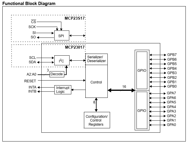
The MCP23S17 implements the Serial Peripheral Interface (SPI) communication interface. The MCP23017 has,

  • I2C communication interface 
  • reset (active high)
  • additional address setting
  • interrupts output
  • two 8-bit bi-directional GPIO, GPA and GPB.
PIC16F887 MCP23017 I2C GPIO Example using XC8
Functional Block Diagram


This chip able to operate at high speed up to 1.7MHz. Its operating voltage ranges from 1.8V to 5.5V. For electronics hobbyist prototyping a 5V stable supply voltage is common.

PIC16F887 MCP23017 I2C GPIO Example using XC8
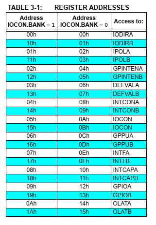
Register Addresses
All registers listed above are configuration registers, status registers, and data registers. It has two memory banks, bank0 and bank1. By default we work with bank0. For example,

  • IODIRA - I/O Direction Register A (0 for output and 1 for input)
  • IODIRB - I/O Direction Register B (0 for output and 1 for input)
  • GPPUA - GPIO Pull-Up Resistor Register A (1 for enable and 0 for disable)
  • GPPUB - GPIO Pull-Up Resistor Register B (1 for enable and 0 for disable)
  • GPIOA - General Purpose I/O Port Register A ( this register is for reading data from PORTA)
  • GPIOB - General Purpose I/O Port Register B ( this register is for reading data from PORTB)
  • OLATA - Output Latch Register A ( this register is for writing data to output PORTA) 
  • OLATB - Output Latch Register B ( this register is for writing data to output PORTB)

For more detail you can see its datasheet

To write to this chip the controller needs to write its slave address of 0x40 (A2...A0 are logic 0) followed by its register address and data. It also have sequential addressing mode but I don't mention it here.

To read from this chip the controller needs to write its slave address 0x40 (A2...A0 are logic 0) followed by its register address. Then start a new write session of the device slave address of 0x41 followed the I2C read mode to get the data.

MPLABX IDE and XC8 Programming 

This introductory example, the master micro-processor just send a LED shifting data to the I2C slave MCP23017 chip. I use the I2C communication module of PIC16F887. Its serial clock frequency is 400kHz.

  1. /*
  2.  * File: main.c
  3.  * Author: Admin
  4.  *
  5.  * Created on January 21, 2024, 3:07 PM
  6.  */
  7.  
  8. #include <xc.h>
  9. #include "config.h"
  10. #include "i2c.h"
  11.  
  12. #define _XTAL_FREQ 8000000UL
  13.  
  14. #define MCP23017_W 0x40
  15. #define MCP23017_R 0x41
  16.  
  17. void mcp23017_write(uint8_t address, uint8_t data){
  18. i2c_start();
  19. i2c_write(MCP23017_W);
  20. i2c_write(address);
  21. i2c_write(data);
  22. i2c_stop();
  23. }
  24.  
  25. void main(void) {
  26. OSCCONbits.IRCF=7;
  27. i2c_init(400000);
  28. mcp23017_write(0,0);
  29. while(1){
  30. uint8_t i=0;
  31. while(i<8){
  32. mcp23017_write(0x14,1<<i);
  33. i++;
  34. __delay_ms(100);
  35. }
  36. }
  37. return;
  38. }
  39.  

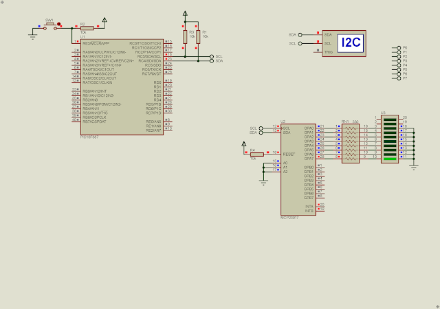
I use only GPA for LED output. The LED shifts for every 100 Milli seconds.

PIC16F887 MCP23017 I2C GPIO Example using XC8
Proteus Simulation
I simulate this program using Proteus VSM 8. Click here to download this example.

The following example, the MCP23017 is used for reading data from GPB and writing data back to GPA.

  1. /*
  2.  * File: main.c
  3.  * Author: Admin
  4.  *
  5.  * Created on January 21, 2024, 4:16 PM
  6.  */
  7.  
  8. #include <xc.h>
  9. #include "config.h"
  10. #include "i2c.h"
  11.  
  12. #define _XTAL_FREQ 8000000UL
  13.  
  14. #define MCP23017_W 0x40
  15. #define MCP23017_R 0x41
  16.  
  17. #define IODIRA 0x00
  18. #define IODIRB 0x01
  19. #define GPPUB 0x0D
  20. #define GPIOB 0x13
  21. #define OLATA 0x14
  22.  
  23. void mcp23017_write(uint8_t address, uint8_t data){
  24. i2c_start();
  25. i2c_write(MCP23017_W);
  26. i2c_write(address);
  27. i2c_write(data);
  28. i2c_stop();
  29. }
  30.  
  31. uint8_t mcp23017_read(uint8_t address){
  32. uint8_t data;
  33. i2c_start();
  34. i2c_write(MCP23017_W);
  35. i2c_write(address);
  36. i2c_stop();
  37.  
  38. i2c_start();
  39. i2c_write(MCP23017_R);
  40. data=i2c_read(0);
  41. i2c_stop();
  42. return data;
  43. }
  44.  
  45. void main(void) {
  46. OSCCONbits.IRCF=7;
  47. i2c_init(400000);
  48. mcp23017_write(IODIRA,0); //GPA AS OUTPUT
  49. mcp23017_write(IODIRB,0xFF); //GPB AS INPUT
  50. mcp23017_write(GPPUB,0xFF); //GPB PULL-UP ENABLE
  51. while(1){
  52. //READ GPB INPUT DATA
  53. uint8_t temp=mcp23017_read(GPIOB);
  54. __delay_ms(10);
  55. //WRITE GPA OUTPUT DATA
  56. mcp23017_write(OLATA,temp);
  57. __delay_ms(50);
  58. }
  59. return;
  60. }
  61.  

I enable its pull-up resistor at GPB without adding additional resistor the the circuit.

PIC16F887 MCP23017 I2C GPIO Example using XC8
Schematic Diagram

Simulating program in Proteus work very well. Click here to download this example.


Thursday, September 14, 2023

STM32F103C8T6 Blue Pill And Character LCD Interfacing In 8-Bit Mode Example

In this ARM programming example, I will use an earlier day character LCD to show text. This character LCD conventionally uses an HD44780 LCD controller manufactured by Hitachi. Currently there are a lot of low cost equivalent LCD controllers.

STM32F103C8T6 Blue Pill And Character LCD Interfacing In 8-Bit Mode Example
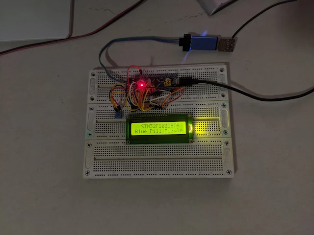
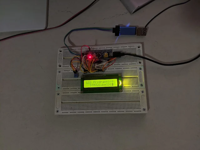
Blue Pill Experiment On Bread Board

I will not write the details about this controller here because it's already explained in previous tutorial. But it uses the ATMega32 AVR micro-controller

STM32F103C8T6 Blue Pill And Character LCD Interfacing In 8-Bit Mode Example
Blue Pill Simulating Program Using Proteus VSM 8.15

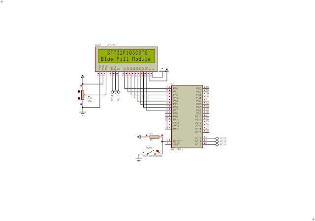
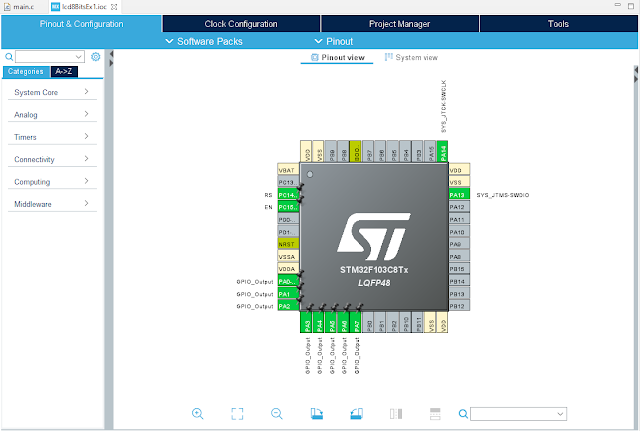
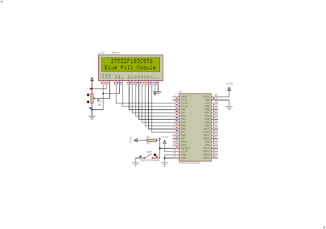
I use the lower nibble of Port A to send command or data to LCD module. PortA is a 16-bit bi-directional I/O. PC14 connects to LCD Register Select (RS) while PC15 connects to LCD En (Enable). As we just needs to send data or command to LCD module, the LCD Read/Write (R/W) just connect to GND.

STM32F103C8T6 Blue Pill And Character LCD Interfacing In 8-Bit Mode Example

GPIO Setting In Device Configuration Tool

Without writing a legacy style C/C++ for ARM micro-controller, I use the Code Configuration Tool inside the STM32CubeIDE. It will generate C/C++ source code whenever we have finish all preferred setting on target MCU. 

STM32F103C8T6 Blue Pill And Character LCD Interfacing In 8-Bit Mode Example
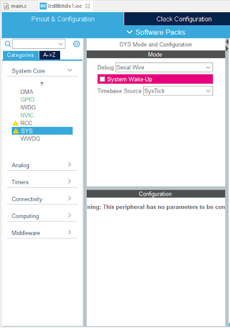
SYS Setting

In SYS tab, I select Serial Wire as the debug interface with ST-LINK V2. The System Wake-Up check box must left unchecked to enable the PA0 as general purpose I/O.

  1. /* USER CODE BEGIN Header */
  2. /**
  3.   ******************************************************************************
  4.   * @file : main.c
  5.   * @brief : Main program body
  6.   ******************************************************************************
  7.   * @attention
  8.   *
  9.   * <h2><center>&copy; Copyright (c) 2023 STMicroelectronics.
  10.   * All rights reserved.</center></h2>
  11.   *
  12.   * This software component is licensed by ST under BSD 3-Clause license,
  13.   * the "License"; You may not use this file except in compliance with the
  14.   * License. You may obtain a copy of the License at:
  15.   * opensource.org/licenses/BSD-3-Clause
  16.   *
  17.   ******************************************************************************
  18.   */
  19. /* USER CODE END Header */
  20. /* Includes ------------------------------------------------------------------*/
  21.  
  22. #include "main.h"
  23.  
  24. void delay(uint16_t num){
  25. for(uint16_t i=0;i<num;i++);
  26. }
  27.  
  28. void lcdCommand(uint16_t cmd){
  29. GPIOA->ODR=cmd;
  30. //GPIOB->ODR&=~(1<<RS_Pin);
  31. HAL_GPIO_WritePin(RS_GPIO_Port,RS_Pin,GPIO_PIN_RESET);
  32. //GPIOB->ODR|=(1<<EN_Pin);
  33. HAL_GPIO_WritePin(EN_GPIO_Port,EN_Pin,GPIO_PIN_SET);
  34. //HAL_Delay(1);
  35. delay(100);
  36. //GPIOB->ODR&=~(1<<EN_Pin);
  37. HAL_GPIO_WritePin(EN_GPIO_Port,EN_Pin,GPIO_PIN_RESET);
  38. //HAL_Delay(10);
  39. delay(10000);
  40. }
  41.  
  42. void lcdData(uint8_t data){
  43. GPIOA->ODR=data;
  44. //GPIOB->ODR|=(1<<RS_Pin);
  45. HAL_GPIO_WritePin(RS_GPIO_Port,RS_Pin,GPIO_PIN_SET);
  46. //GPIOB->ODR|=(1<<EN_Pin);
  47. HAL_GPIO_WritePin(EN_GPIO_Port,EN_Pin,GPIO_PIN_SET);
  48. //HAL_Delay(1);
  49. delay(10);
  50. //GPIOB->ODR&=~(1<<EN_Pin);
  51. HAL_GPIO_WritePin(EN_GPIO_Port,EN_Pin,GPIO_PIN_RESET);
  52. //HAL_Delay(10);
  53. delay(1000);
  54. }
  55.  
  56. void lcdInit(void){
  57. //GPIOB->ODR&=~(1<<RS_Pin);
  58. HAL_GPIO_WritePin(EN_GPIO_Port,EN_Pin,GPIO_PIN_RESET);
  59. //HAL_Delay(2);
  60. delay(20000);
  61. lcdCommand(0x38);
  62. lcdCommand(0x0F);
  63. lcdCommand(0x01);
  64. //HAL_Delay(20);
  65. delay(20000);
  66. lcdCommand(0x06);
  67. }
  68.  
  69. void lcdGotoXy(unsigned char x,unsigned char y){
  70. unsigned char charAddr[]={0x80,0xC0,0x94,0xD4};
  71. lcdCommand(charAddr[y-1]+x-1);
  72. //HAL_Delay(1);
  73. delay(1000);
  74. }
  75.  
  76. void lcdPrint(char *str){
  77. unsigned char i=0;
  78. while(str[i]!=0){
  79. lcdData(str[i]);
  80. i++;
  81. }
  82. }
  83.  
  84. void lcdClear(void){
  85. lcdCommand(0x01);
  86. delay(100);
  87. }
  88.  
  89. /* Private function prototypes -----------------------------------------------*/
  90. void SystemClock_Config(void);
  91. static void MX_GPIO_Init(void);
  92.  
  93. /**
  94.   * @brief The application entry point.
  95.   * @retval int
  96.   */
  97. int main(void)
  98. {
  99. /* Reset of all peripherals, Initializes the Flash interface and the Systick. */
  100. HAL_Init();
  101. /* Configure the system clock */
  102. SystemClock_Config();
  103. /* Initialize all configured peripherals */
  104. MX_GPIO_Init();
  105.  
  106. lcdInit();
  107. lcdGotoXy(3,1);
  108. lcdPrint("STM32F103C8T6");
  109. lcdGotoXy(1,2);
  110. lcdPrint("Blue Pill Module");
  111. for(uint8_t i=0;i<200;i++) delay(50000);
  112. lcdClear();
  113. lcdGotoXy(1,1);
  114. lcdPrint("LCD Programming");
  115. lcdGotoXy(3,2);
  116. lcdPrint("STM32CubeIDE");
  117.  
  118. /* Infinite loop */
  119. /* USER CODE BEGIN WHILE */
  120. while (1)
  121. {
  122.  
  123. }
  124. /* USER CODE END 3 */
  125. }
  126.  
  127. /**
  128.   * @brief System Clock Configuration
  129.   * @retval None
  130.   */
  131. void SystemClock_Config(void)
  132. {
  133. RCC_OscInitTypeDef RCC_OscInitStruct = {0};
  134. RCC_ClkInitTypeDef RCC_ClkInitStruct = {0};
  135.  
  136. /** Initializes the RCC Oscillators according to the specified parameters
  137.   * in the RCC_OscInitTypeDef structure.
  138.   */
  139. RCC_OscInitStruct.OscillatorType = RCC_OSCILLATORTYPE_HSI;
  140. RCC_OscInitStruct.HSIState = RCC_HSI_ON;
  141. RCC_OscInitStruct.HSICalibrationValue = RCC_HSICALIBRATION_DEFAULT;
  142. RCC_OscInitStruct.PLL.PLLState = RCC_PLL_NONE;
  143. if (HAL_RCC_OscConfig(&RCC_OscInitStruct) != HAL_OK)
  144. {
  145. Error_Handler();
  146. }
  147. /** Initializes the CPU, AHB and APB buses clocks
  148.   */
  149. RCC_ClkInitStruct.ClockType = RCC_CLOCKTYPE_HCLK|RCC_CLOCKTYPE_SYSCLK
  150. |RCC_CLOCKTYPE_PCLK1|RCC_CLOCKTYPE_PCLK2;
  151. RCC_ClkInitStruct.SYSCLKSource = RCC_SYSCLKSOURCE_HSI;
  152. RCC_ClkInitStruct.AHBCLKDivider = RCC_SYSCLK_DIV1;
  153. RCC_ClkInitStruct.APB1CLKDivider = RCC_HCLK_DIV1;
  154. RCC_ClkInitStruct.APB2CLKDivider = RCC_HCLK_DIV1;
  155.  
  156. if (HAL_RCC_ClockConfig(&RCC_ClkInitStruct, FLASH_LATENCY_0) != HAL_OK)
  157. {
  158. Error_Handler();
  159. }
  160. }
  161.  
  162. /**
  163.   * @brief GPIO Initialization Function
  164.   * @param None
  165.   * @retval None
  166.   */
  167. static void MX_GPIO_Init(void)
  168. {
  169. GPIO_InitTypeDef GPIO_InitStruct = {0};
  170.  
  171. /* GPIO Ports Clock Enable */
  172. __HAL_RCC_GPIOC_CLK_ENABLE();
  173. __HAL_RCC_GPIOA_CLK_ENABLE();
  174.  
  175. /*Configure GPIO pin Output Level */
  176. HAL_GPIO_WritePin(GPIOC, RS_Pin|EN_Pin, GPIO_PIN_RESET);
  177.  
  178. /*Configure GPIO pin Output Level */
  179. HAL_GPIO_WritePin(GPIOA, GPIO_PIN_0|GPIO_PIN_1|GPIO_PIN_2|GPIO_PIN_3
  180. |GPIO_PIN_4|GPIO_PIN_5|GPIO_PIN_6|GPIO_PIN_7, GPIO_PIN_RESET);
  181.  
  182. /*Configure GPIO pins : RS_Pin EN_Pin */
  183. GPIO_InitStruct.Pin = RS_Pin|EN_Pin;
  184. GPIO_InitStruct.Mode = GPIO_MODE_OUTPUT_PP;
  185. GPIO_InitStruct.Pull = GPIO_NOPULL;
  186. GPIO_InitStruct.Speed = GPIO_SPEED_FREQ_LOW;
  187. HAL_GPIO_Init(GPIOC, &GPIO_InitStruct);
  188.  
  189. /*Configure GPIO pins : PA0 PA1 PA2 PA3
  190.   PA4 PA5 PA6 PA7 */
  191. GPIO_InitStruct.Pin = GPIO_PIN_0|GPIO_PIN_1|GPIO_PIN_2|GPIO_PIN_3
  192. |GPIO_PIN_4|GPIO_PIN_5|GPIO_PIN_6|GPIO_PIN_7;
  193. GPIO_InitStruct.Mode = GPIO_MODE_OUTPUT_PP;
  194. GPIO_InitStruct.Pull = GPIO_NOPULL;
  195. GPIO_InitStruct.Speed = GPIO_SPEED_FREQ_LOW;
  196. HAL_GPIO_Init(GPIOA, &GPIO_InitStruct);
  197.  
  198. }
  199.  
  200. /* USER CODE BEGIN 4 */
  201.  
  202. /* USER CODE END 4 */
  203.  
  204. /**
  205.   * @brief This function is executed in case of error occurrence.
  206.   * @retval None
  207.   */
  208. void Error_Handler(void)
  209. {
  210. /* USER CODE BEGIN Error_Handler_Debug */
  211. /* User can add his own implementation to report the HAL error return state */
  212. __disable_irq();
  213. while (1)
  214. {
  215. }
  216. /* USER CODE END Error_Handler_Debug */
  217. }
  218.  
  219. #ifdef USE_FULL_ASSERT
  220. /**
  221.   * @brief Reports the name of the source file and the source line number
  222.   * where the assert_param error has occurred.
  223.   * @param file: pointer to the source file name
  224.   * @param line: assert_param error line source number
  225.   * @retval None
  226.   */
  227. void assert_failed(uint8_t *file, uint32_t line)
  228. {
  229. /* USER CODE BEGIN 6 */
  230. /* User can add his own implementation to report the file name and line number,
  231.   ex: printf("Wrong parameters value: file %s on line %d\r\n", file, line) */
  232. /* USER CODE END 6 */
  233. }
  234. #endif /* USE_FULL_ASSERT */
  235.  
  236. /************************ (C) COPYRIGHT STMicroelectronics *****END OF FILE****/
  237.  

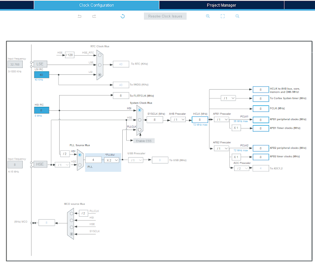
I use its internal HSI RC clock source. However this module has an external 8MHz crystal oscillator. Click here to download its source file.

STM32F103C8T6 Blue Pill And Character LCD Interfacing In 8-Bit Mode Example

Clock Configuration

I re-arrange the Blue Pill model in Proteus VSM 8.15. I want to make its pin map similar to the physical hardware.

STM32F103C8T6 Blue Pill And Character LCD Interfacing In 8-Bit Mode Example
Schematic Diagram


STM32F103C8T6 Blue Pill And Character LCD Interfacing In 8-Bit Mode Example
Top View #1


STM32F103C8T6 Blue Pill And Character LCD Interfacing In 8-Bit Mode Example
Top View #2

However it can simulate like the original model. The STM32 Blue Pill supply voltage is +3.3V while the LCD module supply voltage is +5V. The USB power bus gives the module a stable +5V DC voltage. I use another micro USB cable connects to the USB header on the STM32 Blue Pill module.

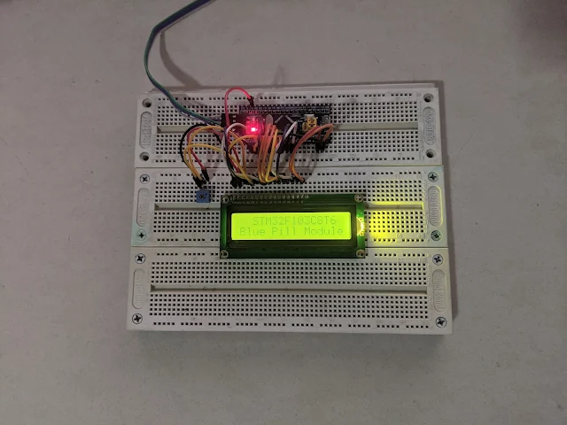
STM32F103C8T6 Blue Pill And Character LCD Interfacing In 8-Bit Mode Example
Using A +3.3V Supply Voltage For The LCD Module

However we can connect these modules to +5.0V supply voltage from the ST-LINK V2 debugger. As shown in the picture above, using a +3.3V supply for LCD module causing an insufficient power that make the display data unclear.


320x50

Search This Blog

Labels

25AA010A (1) 8051 (7) 93AA46B (1) ADC (30) Analog Comparator (1) Arduino (15) ARM (6) AT89C52 (7) ATMega32 (57) AVR (58) CCS PICC (28) DAC (1) DHT11 (2) Display (106) Distance Sensor (3) DS18B20 (3) dsPIC (3) dsPIC30F1010 (3) dsPIC30F2010 (1) EEPROM (5) Environment Sensor (4) esp8266 (1) I2C (29) Input/Output (68) Interrupt (19) Keil (5) Keypad (10) LCD (48) Master/Slave (1) MAX7221 (1) MCP23017 (5) MCP23S17 (4) Meter (3) MikroC (2) Motor (15) MPLABX (73) Nokia 5110 LCD (3) OLED (2) One-Wire (6) Oscillator (8) PCB (10) PCD8544 (3) PCF8574 (5) PIC (108) PIC12F (3) PIC16F628A (3) PIC16F630 (2) PIC16F716 (4) PIC16F818 (11) PIC16F818/819 (3) PIC16F84A (16) PIC16F876A (2) PIC16F877A (9) PIC16F88 (2) PIC16F887 (60) PIC18 (19) PIC18F1220 (5) PIC18F2550 (5) PIC18F4550 (12) PICKit2 (1) PWM (11) RTC (9) Sensor (11) SH1106 (1) Shift Register (11) Shift Registers (3) SPI (24) STM32 (6) STM32 Blue Pill (6) STM32CubeIDE (6) STM32F103C8T6 (6) SysTick (3) temperature sensor (11) Thermometer (21) Timer/Counter (31) TM1637 (2) UART (7) Ultrasonic (4) Voltmeter (7) WDT (1) XC16 (2) XC8 (96)

tyro-728x90