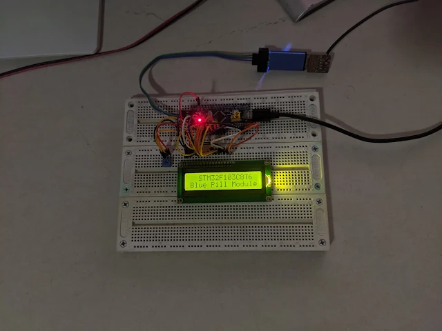
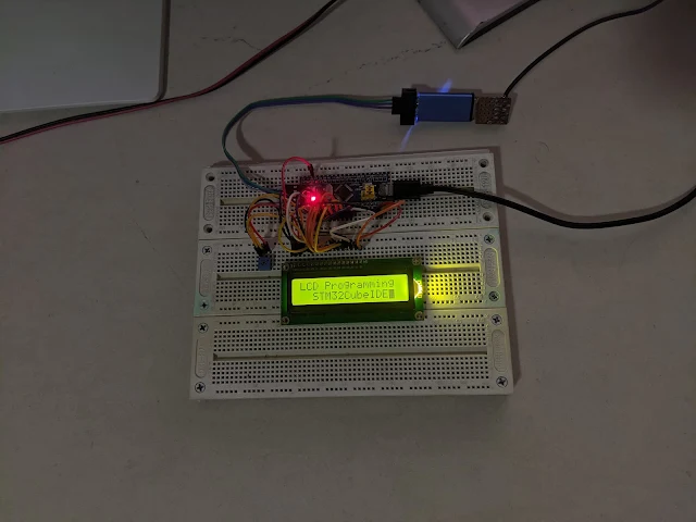
In this ARM programming example, I will use an earlier day character LCD to show text. This character LCD conventionally uses an HD44780 LCD controller manufactured by Hitachi. Currently there are a lot of low cost equivalent LCD controllers.
Blue Pill Experiment On Bread Board |
I will not write the details about this controller here because it's already explained in previous tutorial. But it uses the ATMega32 AVR micro-controller.
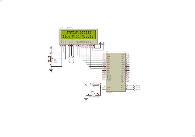
Blue Pill Simulating Program Using Proteus VSM 8.15 |
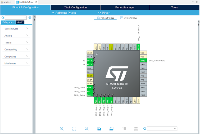
I use the lower nibble of Port A to send command or data to LCD module. PortA is a 16-bit bi-directional I/O. PC14 connects to LCD Register Select (RS) while PC15 connects to LCD En (Enable). As we just needs to send data or command to LCD module, the LCD Read/Write (R/W) just connect to GND.
GPIO Setting In Device Configuration Tool |
Without writing a legacy style C/C++ for ARM micro-controller, I use the Code Configuration Tool inside the STM32CubeIDE. It will generate C/C++ source code whenever we have finish all preferred setting on target MCU.
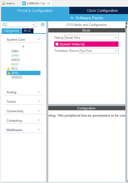
SYS Setting |
In SYS tab, I select Serial Wire as the debug interface with ST-LINK V2. The System Wake-Up check box must left unchecked to enable the PA0 as general purpose I/O.
/* USER CODE BEGIN Header */ /** ****************************************************************************** * @file : main.c * @brief : Main program body ****************************************************************************** * @attention * * <h2><center>© Copyright (c) 2023 STMicroelectronics. * All rights reserved.</center></h2> * * This software component is licensed by ST under BSD 3-Clause license, * the "License"; You may not use this file except in compliance with the * License. You may obtain a copy of the License at: * opensource.org/licenses/BSD-3-Clause * ****************************************************************************** */ /* USER CODE END Header */ /* Includes ------------------------------------------------------------------*/ #include "main.h" void delay(uint16_t num){ for(uint16_t i=0;i<num;i++); } void lcdCommand(uint16_t cmd){ GPIOA->ODR=cmd; //GPIOB->ODR&=~(1<<RS_Pin); HAL_GPIO_WritePin(RS_GPIO_Port,RS_Pin,GPIO_PIN_RESET); //GPIOB->ODR|=(1<<EN_Pin); HAL_GPIO_WritePin(EN_GPIO_Port,EN_Pin,GPIO_PIN_SET); //HAL_Delay(1); delay(100); //GPIOB->ODR&=~(1<<EN_Pin); HAL_GPIO_WritePin(EN_GPIO_Port,EN_Pin,GPIO_PIN_RESET); //HAL_Delay(10); delay(10000); } void lcdData(uint8_t data){ GPIOA->ODR=data; //GPIOB->ODR|=(1<<RS_Pin); HAL_GPIO_WritePin(RS_GPIO_Port,RS_Pin,GPIO_PIN_SET); //GPIOB->ODR|=(1<<EN_Pin); HAL_GPIO_WritePin(EN_GPIO_Port,EN_Pin,GPIO_PIN_SET); //HAL_Delay(1); delay(10); //GPIOB->ODR&=~(1<<EN_Pin); HAL_GPIO_WritePin(EN_GPIO_Port,EN_Pin,GPIO_PIN_RESET); //HAL_Delay(10); delay(1000); } void lcdInit(void){ //GPIOB->ODR&=~(1<<RS_Pin); HAL_GPIO_WritePin(EN_GPIO_Port,EN_Pin,GPIO_PIN_RESET); //HAL_Delay(2); delay(20000); lcdCommand(0x38); lcdCommand(0x0F); lcdCommand(0x01); //HAL_Delay(20); delay(20000); lcdCommand(0x06); } void lcdGotoXy(unsigned char x,unsigned char y){ unsigned char charAddr[]={0x80,0xC0,0x94,0xD4}; lcdCommand(charAddr[y-1]+x-1); //HAL_Delay(1); delay(1000); } void lcdPrint(char *str){ unsigned char i=0; while(str[i]!=0){ lcdData(str[i]); i++; } } void lcdClear(void){ lcdCommand(0x01); delay(100); } /* Private function prototypes -----------------------------------------------*/ void SystemClock_Config(void); static void MX_GPIO_Init(void); /** * @brief The application entry point. * @retval int */ int main(void) { /* Reset of all peripherals, Initializes the Flash interface and the Systick. */ HAL_Init(); /* Configure the system clock */ SystemClock_Config(); /* Initialize all configured peripherals */ MX_GPIO_Init(); lcdInit(); lcdGotoXy(3,1); lcdPrint("STM32F103C8T6"); lcdGotoXy(1,2); lcdPrint("Blue Pill Module"); for(uint8_t i=0;i<200;i++) delay(50000); lcdClear(); lcdGotoXy(1,1); lcdPrint("LCD Programming"); lcdGotoXy(3,2); lcdPrint("STM32CubeIDE"); /* Infinite loop */ /* USER CODE BEGIN WHILE */ while (1) { } /* USER CODE END 3 */ } /** * @brief System Clock Configuration * @retval None */ void SystemClock_Config(void) { RCC_OscInitTypeDef RCC_OscInitStruct = {0}; RCC_ClkInitTypeDef RCC_ClkInitStruct = {0}; /** Initializes the RCC Oscillators according to the specified parameters * in the RCC_OscInitTypeDef structure. */ RCC_OscInitStruct.OscillatorType = RCC_OSCILLATORTYPE_HSI; RCC_OscInitStruct.HSIState = RCC_HSI_ON; RCC_OscInitStruct.HSICalibrationValue = RCC_HSICALIBRATION_DEFAULT; RCC_OscInitStruct.PLL.PLLState = RCC_PLL_NONE; if (HAL_RCC_OscConfig(&RCC_OscInitStruct) != HAL_OK) { Error_Handler(); } /** Initializes the CPU, AHB and APB buses clocks */ RCC_ClkInitStruct.ClockType = RCC_CLOCKTYPE_HCLK|RCC_CLOCKTYPE_SYSCLK |RCC_CLOCKTYPE_PCLK1|RCC_CLOCKTYPE_PCLK2; RCC_ClkInitStruct.SYSCLKSource = RCC_SYSCLKSOURCE_HSI; RCC_ClkInitStruct.AHBCLKDivider = RCC_SYSCLK_DIV1; RCC_ClkInitStruct.APB1CLKDivider = RCC_HCLK_DIV1; RCC_ClkInitStruct.APB2CLKDivider = RCC_HCLK_DIV1; if (HAL_RCC_ClockConfig(&RCC_ClkInitStruct, FLASH_LATENCY_0) != HAL_OK) { Error_Handler(); } } /** * @brief GPIO Initialization Function * @param None * @retval None */ static void MX_GPIO_Init(void) { GPIO_InitTypeDef GPIO_InitStruct = {0}; /* GPIO Ports Clock Enable */ __HAL_RCC_GPIOC_CLK_ENABLE(); __HAL_RCC_GPIOA_CLK_ENABLE(); /*Configure GPIO pin Output Level */ HAL_GPIO_WritePin(GPIOC, RS_Pin|EN_Pin, GPIO_PIN_RESET); /*Configure GPIO pin Output Level */ HAL_GPIO_WritePin(GPIOA, GPIO_PIN_0|GPIO_PIN_1|GPIO_PIN_2|GPIO_PIN_3 |GPIO_PIN_4|GPIO_PIN_5|GPIO_PIN_6|GPIO_PIN_7, GPIO_PIN_RESET); /*Configure GPIO pins : RS_Pin EN_Pin */ GPIO_InitStruct.Pin = RS_Pin|EN_Pin; GPIO_InitStruct.Mode = GPIO_MODE_OUTPUT_PP; GPIO_InitStruct.Pull = GPIO_NOPULL; GPIO_InitStruct.Speed = GPIO_SPEED_FREQ_LOW; HAL_GPIO_Init(GPIOC, &GPIO_InitStruct); /*Configure GPIO pins : PA0 PA1 PA2 PA3 PA4 PA5 PA6 PA7 */ GPIO_InitStruct.Pin = GPIO_PIN_0|GPIO_PIN_1|GPIO_PIN_2|GPIO_PIN_3 |GPIO_PIN_4|GPIO_PIN_5|GPIO_PIN_6|GPIO_PIN_7; GPIO_InitStruct.Mode = GPIO_MODE_OUTPUT_PP; GPIO_InitStruct.Pull = GPIO_NOPULL; GPIO_InitStruct.Speed = GPIO_SPEED_FREQ_LOW; HAL_GPIO_Init(GPIOA, &GPIO_InitStruct); } /* USER CODE BEGIN 4 */ /* USER CODE END 4 */ /** * @brief This function is executed in case of error occurrence. * @retval None */ void Error_Handler(void) { /* USER CODE BEGIN Error_Handler_Debug */ /* User can add his own implementation to report the HAL error return state */ __disable_irq(); while (1) { } /* USER CODE END Error_Handler_Debug */ } #ifdef USE_FULL_ASSERT /** * @brief Reports the name of the source file and the source line number * where the assert_param error has occurred. * @param file: pointer to the source file name * @param line: assert_param error line source number * @retval None */ void assert_failed(uint8_t *file, uint32_t line) { /* USER CODE BEGIN 6 */ /* User can add his own implementation to report the file name and line number, ex: printf("Wrong parameters value: file %s on line %d\r\n", file, line) */ /* USER CODE END 6 */ } #endif /* USE_FULL_ASSERT */ /************************ (C) COPYRIGHT STMicroelectronics *****END OF FILE****/
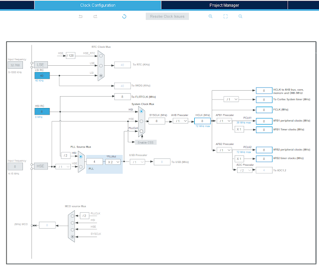
I use its internal HSI RC clock source. However this module has an external 8MHz crystal oscillator. Click here to download its source file.
Clock Configuration |
I re-arrange the Blue Pill model in Proteus VSM 8.15. I want to make its pin map similar to the physical hardware.
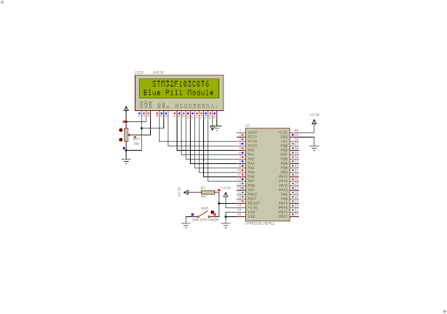
Schematic Diagram |
Top View #1 |
Top View #2 |
However it can simulate like the original model. The STM32 Blue Pill supply voltage is +3.3V while the LCD module supply voltage is +5V. The USB power bus gives the module a stable +5V DC voltage. I use another micro USB cable connects to the USB header on the STM32 Blue Pill module.
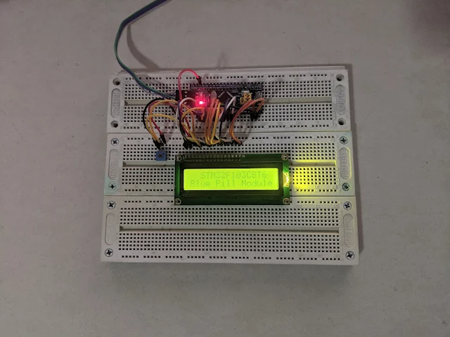
Using A +3.3V Supply Voltage For The LCD Module |
However we can connect these modules to +5.0V supply voltage from the ST-LINK V2 debugger. As shown in the picture above, using a +3.3V supply for LCD module causing an insufficient power that make the display data unclear.
No comments:
Post a Comment