Wednesday, August 31, 2022

Getting Started With STM32F103C8T6 Module with STM32CubeIDE

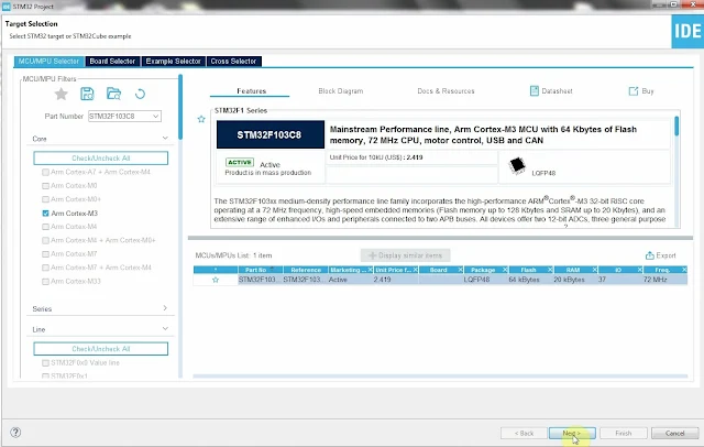
STM32F103C8T6 module is a 32-bit ARM Cortex-M3 CPU. I could operate up to 72MHz. Its Flash memory is 64kBytes, with its internal SRAM of 20kBytes. A popular chip in use is a 48-pin LQFP package. 

Getting Started WithSTM32F103C8T6 Module with STM32CubeIDE
STM32F103C8T6 module

A typical module is made from the STM32F103C8T6 chip. It's a 44-pin chip.

Getting Started With STM32F103C8T6 Module with STM32CubeIDE
A clone version of ST-LINK V2

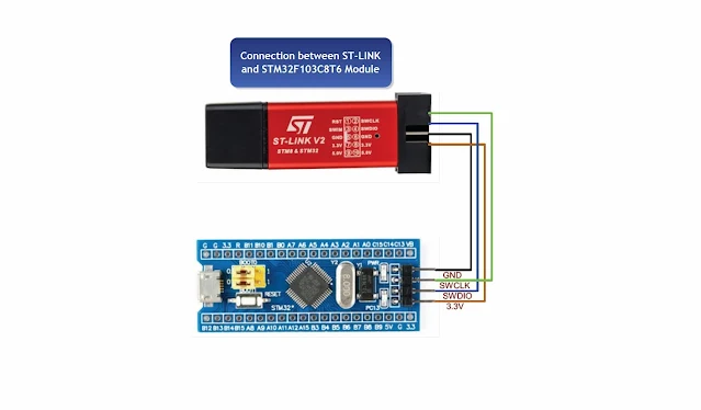
This programmer is very simple, and easy to use with only four pins.

The STM32CubeIDE is an IDE from this device vendor. It's free to use. To get started with this IDE and the STM32F103C8T6 module. We will start a LED blinking program. Now I have downloaded and installed this program on my PC.

Getting Started With STM32F103C8T6 Module with STM32CubeIDE

Getting Started With STM32F103C8T6 Module with STM32CubeIDE
#1

Getting Started With STM32F103C8T6 Module with STM32CubeIDE
#2
Getting Started With STM32F103C8T6 Module with STM32CubeIDE
Name this project and click next

Getting Started With STM32F103C8T6 Module with STM32CubeIDE
Click on Finish

Getting Started With STM32F103C8T6 Module with STM32CubeIDE
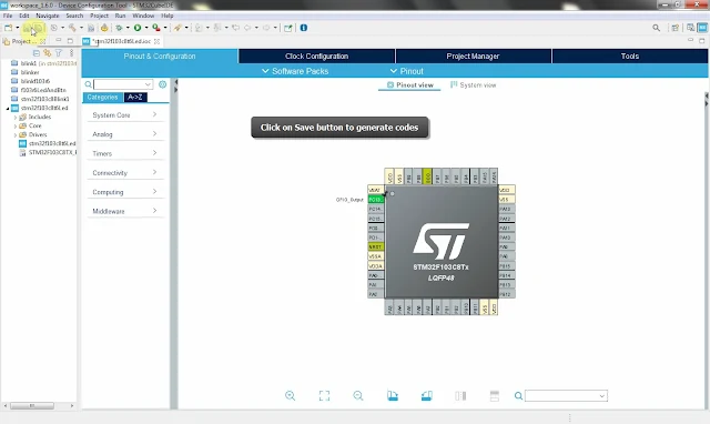
Select PC13 as GPIO_OUTPUT  
Getting Started With STM32F103C8T6 Module with STM32CubeIDE
Click on save button to generate code

Getting Started With STM32F103C8T6 Module with STM32CubeIDE
Write C code in editor window

Getting Started With STM32F103C8T6 Module with STM32CubeIDE
And build this project

Its C source code look like below.

  1. /* USER CODE BEGIN Header */
  2. /**
  3.   ******************************************************************************
  4.   * @file : main.c
  5.   * @brief : Main program body
  6.   ******************************************************************************
  7.   * @attention
  8.   *
  9.   * <h2><center>&copy; Copyright (c) 2022 STMicroelectronics.
  10.   * All rights reserved.</center></h2>
  11.   *
  12.   * This software component is licensed by ST under BSD 3-Clause license,
  13.   * the "License"; You may not use this file except in compliance with the
  14.   * License. You may obtain a copy of the License at:
  15.   * opensource.org/licenses/BSD-3-Clause
  16.   *
  17.   ******************************************************************************
  18.   */
  19. /* USER CODE END Header */
  20. /* Includes ------------------------------------------------------------------*/
  21. #include "main.h"
  22.  
  23. /* Private function prototypes -----------------------------------------------*/
  24. void SystemClock_Config(void);
  25. static void MX_GPIO_Init(void);
  26. /* USER CODE BEGIN PFP */
  27.  
  28. /* USER CODE END PFP */
  29.  
  30. /* Private user code ---------------------------------------------------------*/
  31. /* USER CODE BEGIN 0 */
  32.  
  33. /* USER CODE END 0 */
  34.  
  35. /**
  36.   * @brief The application entry point.
  37.   * @retval int
  38.   */
  39. int main(void)
  40. {
  41. /* USER CODE BEGIN 1 */
  42.  
  43. /* USER CODE END 1 */
  44.  
  45. /* MCU Configuration--------------------------------------------------------*/
  46.  
  47. /* Reset of all peripherals, Initializes the Flash interface and the Systick. */
  48. HAL_Init();
  49.  
  50. /* USER CODE BEGIN Init */
  51.  
  52. /* USER CODE END Init */
  53.  
  54. /* Configure the system clock */
  55. SystemClock_Config();
  56.  
  57. /* USER CODE BEGIN SysInit */
  58.  
  59. /* USER CODE END SysInit */
  60.  
  61. /* Initialize all configured peripherals */
  62. MX_GPIO_Init();
  63. /* USER CODE BEGIN 2 */
  64.  
  65. /* USER CODE END 2 */
  66.  
  67. /* Infinite loop */
  68. /* USER CODE BEGIN WHILE */
  69. while (1)
  70. {
  71. //Toggle PC13
  72. HAL_GPIO_TogglePin(GPIOC,GPIO_PIN_13);
  73. //Wait for 1 second
  74. HAL_Delay(1000);
  75. }
  76. /* USER CODE END 3 */
  77. }
  78.  
  79. /**
  80.   * @brief System Clock Configuration
  81.   * @retval None
  82.   */
  83. void SystemClock_Config(void)
  84. {
  85. RCC_OscInitTypeDef RCC_OscInitStruct = {0};
  86. RCC_ClkInitTypeDef RCC_ClkInitStruct = {0};
  87.  
  88. /** Initializes the RCC Oscillators according to the specified parameters
  89.   * in the RCC_OscInitTypeDef structure.
  90.   */
  91. RCC_OscInitStruct.OscillatorType = RCC_OSCILLATORTYPE_HSI;
  92. RCC_OscInitStruct.HSIState = RCC_HSI_ON;
  93. RCC_OscInitStruct.HSICalibrationValue = RCC_HSICALIBRATION_DEFAULT;
  94. RCC_OscInitStruct.PLL.PLLState = RCC_PLL_NONE;
  95. if (HAL_RCC_OscConfig(&RCC_OscInitStruct) != HAL_OK)
  96. {
  97. Error_Handler();
  98. }
  99. /** Initializes the CPU, AHB and APB buses clocks
  100.   */
  101. RCC_ClkInitStruct.ClockType = RCC_CLOCKTYPE_HCLK|RCC_CLOCKTYPE_SYSCLK
  102. |RCC_CLOCKTYPE_PCLK1|RCC_CLOCKTYPE_PCLK2;
  103. RCC_ClkInitStruct.SYSCLKSource = RCC_SYSCLKSOURCE_HSI;
  104. RCC_ClkInitStruct.AHBCLKDivider = RCC_SYSCLK_DIV1;
  105. RCC_ClkInitStruct.APB1CLKDivider = RCC_HCLK_DIV1;
  106. RCC_ClkInitStruct.APB2CLKDivider = RCC_HCLK_DIV1;
  107.  
  108. if (HAL_RCC_ClockConfig(&RCC_ClkInitStruct, FLASH_LATENCY_0) != HAL_OK)
  109. {
  110. Error_Handler();
  111. }
  112. }
  113.  
  114. /**
  115.   * @brief GPIO Initialization Function
  116.   * @param None
  117.   * @retval None
  118.   */
  119. static void MX_GPIO_Init(void)
  120. {
  121. GPIO_InitTypeDef GPIO_InitStruct = {0};
  122.  
  123. /* GPIO Ports Clock Enable */
  124. __HAL_RCC_GPIOC_CLK_ENABLE();
  125.  
  126. /*Configure GPIO pin Output Level */
  127. HAL_GPIO_WritePin(GPIOC, GPIO_PIN_13, GPIO_PIN_RESET);
  128.  
  129. /*Configure GPIO pin : PC13 */
  130. GPIO_InitStruct.Pin = GPIO_PIN_13;
  131. GPIO_InitStruct.Mode = GPIO_MODE_OUTPUT_PP;
  132. GPIO_InitStruct.Pull = GPIO_NOPULL;
  133. GPIO_InitStruct.Speed = GPIO_SPEED_FREQ_LOW;
  134. HAL_GPIO_Init(GPIOC, &GPIO_InitStruct);
  135.  
  136. }
  137.  
  138. /* USER CODE BEGIN 4 */
  139.  
  140. /* USER CODE END 4 */
  141.  
  142. /**
  143.   * @brief This function is executed in case of error occurrence.
  144.   * @retval None
  145.   */
  146. void Error_Handler(void)
  147. {
  148. /* USER CODE BEGIN Error_Handler_Debug */
  149. /* User can add his own implementation to report the HAL error return state */
  150. __disable_irq();
  151. while (1)
  152. {
  153. }
  154. /* USER CODE END Error_Handler_Debug */
  155. }
  156.  
  157. #ifdef USE_FULL_ASSERT
  158. /**
  159.   * @brief Reports the name of the source file and the source line number
  160.   * where the assert_param error has occurred.
  161.   * @param file: pointer to the source file name
  162.   * @param line: assert_param error line source number
  163.   * @retval None
  164.   */
  165. void assert_failed(uint8_t *file, uint32_t line)
  166. {
  167. /* USER CODE BEGIN 6 */
  168. /* User can add his own implementation to report the file name and line number,
  169.   ex: printf("Wrong parameters value: file %s on line %d\r\n", file, line) */
  170. /* USER CODE END 6 */
  171. }
  172. #endif /* USE_FULL_ASSERT */
  173.  
  174. /************************ (C) COPYRIGHT STMicroelectronics *****END OF FILE****/
  175.  

 After we build this project, we will need to upload its binary file to the module.

Getting Started With STM32F103C8T6 Module with STM32CubeIDE
Wiring Diagram

I use ST-LINK software because I didn't update its firmware. If we its firmware update, we can use the ST-LINK V2 programmer in STM32CubeIDE.

Getting Started With STM32F103C8T6 Module with STM32CubeIDE
Click on connect

Getting Started With STM32F103C8T6 Module with STM32CubeIDE
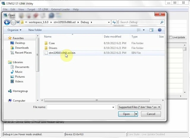
Click on Open button to find bin file

Getting Started With STM32F103C8T6 Module with STM32CubeIDE
Double click on bin file to open
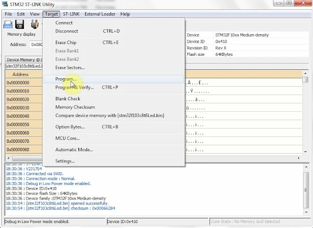
Getting Started With STM32F103C8T6 Module with STM32CubeIDE
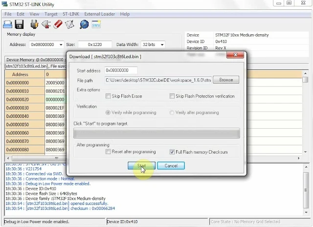
Click on Program

Getting Started With STM32F103C8T6 Module with STM32CubeIDE
Click on Start button

Getting Started With STM32F103C8T6 Module with STM32CubeIDE
When programming finish

I test it on breadboard.

Getting Started With STM32F103C8T6 Module with STM32CubeIDE
Breadboard Experiment

Click here to download its source file.

For other similar posts please check,

  1. Getting Started With STM32F103C8T6 Module with STM32CubeIDE
  2.  STM32F103C8T6 Blue Pill SysTick and Multiplexing Display Example
  3.  STM32F103C8T6 Blue Pill Switch And Multiplexing Display Interface Using SysTick
  4.  STM32F103C8T6 Blue Pill SysTick LED Blinking

Tuesday, August 2, 2022

PIC18F4550 Programming Using MPLabX

PIC18F4550 is an enhanced Flash micro-controller with USB 2.0 feature. This device can operate up to 48MHz that yield the executing speed up to 12MIPS.

PIC18F4550 Programming in MPLabX
PIC18F4550 Family Data Summary

PIC18F4550 Programming in MPLabX

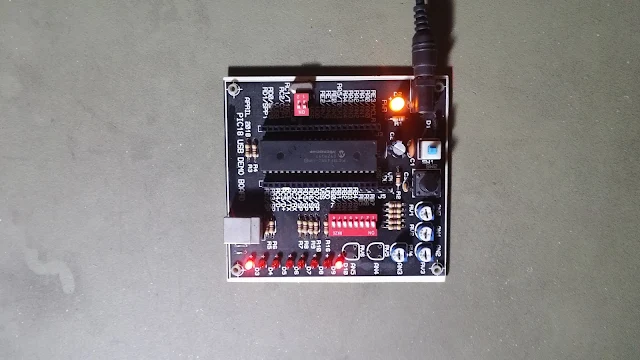
Program testing on target board

 There are some compilers available to program this device,

  • MPLABX XC8
  • MikroC Pro for PIC
  • IAR for PIC18
  • CCS PICC, and etc.

MPLABX XC8 is a free compiler from this device manufacturer. We can buy a paid version for a higher code generation quality.

In this example I use the MPLABX IDE to get start with this device programming. I use the latest version of MPLABX of 6.0, and the XC8 compiler of 2.40.

The program will chase the output LED(s) connect to PORTD.

PIC18F4550 Programming in MPLabX
Schematic
Source Code:

  1. /*
  2.  * File: main.c
  3.  * Author: aki-technical
  4.  *
  5.  * Created on August 1, 2022, 6:22 PM
  6.  */
  7.  
  8. #include <xc.h>
  9. #include "config18f4550.h"
  10.  
  11. #define _XTAL_FREQ 20000000
  12.  
  13. void main(void) {
  14. PORTD=0x00;
  15. LATD=0x00;
  16. TRISD=0x00;
  17. LATD=0x01;
  18. while(1){
  19. LATD=0x01;
  20. while(LATD!=0){
  21. LATD<<=1;
  22. __delay_ms(50);
  23. }
  24. }
  25. return;
  26. }
  27.  

Configuration File:

  1. // CONFIG1L
  2. #pragma config PLLDIV = 1
  3. #pragma config CPUDIV = OSC1_PLL2
  4. #pragma config USBDIV = 1
  5.  
  6. // CONFIG1H
  7. #pragma config FOSC = HS
  8. #pragma config FCMEN = OFF
  9. #pragma config IESO = OFF
  10. // CONFIG2L
  11. #pragma config PWRT = OFF
  12. #pragma config BOR = OFF
  13. #pragma config BORV = 3
  14. #pragma config VREGEN = OFF
  15.  
  16. // CONFIG2H
  17. #pragma config WDT = OFF
  18. #pragma config WDTPS = 32768
  19.  
  20. // CONFIG3H
  21. #pragma config CCP2MX = OFF
  22. #pragma config PBADEN = OFF
  23. #pragma config LPT1OSC = OFF
  24. #pragma config MCLRE = ON
  25.  
  26. // CONFIG4L
  27. #pragma config STVREN = OFF
  28. #pragma config LVP = OFF
  29. #pragma config ICPRT = OFF
  30. #pragma config XINST = OFF
  31.  
  32. // CONFIG5L
  33. #pragma config CP0 = OFF
  34. #pragma config CP1 = OFF
  35. #pragma config CP2 = OFF
  36. #pragma config CP3 = OFF
  37.  
  38. // CONFIG5H
  39. #pragma config CPB = OFF
  40. #pragma config CPD = OFF
  41.  
  42. // CONFIG6L
  43. #pragma config WRT0 = OFF
  44. #pragma config WRT1 = OFF
  45. #pragma config WRT2 = OFF
  46. #pragma config WRT3 = OFF
  47.  
  48. // CONFIG6H
  49. #pragma config WRTC = OFF
  50. #pragma config WRTB = OFF
  51. #pragma config WRTD = OFF
  52.  
  53. // CONFIG7L
  54. #pragma config EBTR0 = OFF
  55. #pragma config EBTR1 = OFF
  56. #pragma config EBTR2 = OFF
  57. #pragma config EBTR3 = OFF
  58.  
  59. // CONFIG7H
  60. #pragma config EBTRB = OFF
  61.  

Click here to download its source file. I use Protues 8.10 SP3 to simulate this program. Now let try an random LED output on PORTD.

  1. /*
  2.  * File: main.c
  3.  * Author: aki-technical
  4.  *
  5.  * Created on August 1, 2022, 6:22 PM
  6.  */
  7.  
  8. #include <xc.h>
  9. #include "config18f4550.h"
  10.  
  11. #define _XTAL_FREQ 20000000
  12.  
  13. void main(void) {
  14. PORTD=0x00;
  15. LATD=0x00;
  16. TRISD=0x00;
  17. LATD=0x01;
  18. while(1){
  19. LATD=rand();
  20. __delay_ms(50);
  21. }
  22. return;
  23. }
  24.  

The schematic diagram remains the same as the previous one's.


Search This Blog

Labels

25AA010A (1) 8051 (7) 93AA46B (1) ADC (30) Analog Comparator (1) Arduino (15) ARM (6) AT89C52 (7) ATMega32 (54) AVR (57) CCS PICC (28) DAC (1) DHT11 (2) Display (105) Distance Sensor (3) DS18B20 (3) dsPIC (2) dsPIC30F1010 (2) EEPROM (5) Environment Sensor (4) esp8266 (1) I2C (29) Input/Output (67) Interrupt (19) Keil (5) Keypad (10) LCD (46) Master/Slave (1) MAX7221 (1) MCP23017 (5) MCP23S17 (4) Meter (3) MikroC (2) Motor (15) MPLABX (66) Nokia 5110 LCD (3) OLED (2) One-Wire (6) Oscillator (8) PCB (6) PCD8544 (3) PCF8574 (5) PIC (107) PIC12F (2) PIC16F628A (2) PIC16F630 (1) PIC16F716 (3) PIC16F818 (10) PIC16F818/819 (2) PIC16F84A (15) PIC16F876A (1) PIC16F877A (9) PIC16F88 (1) PIC16F887 (60) PIC18 (19) PIC18F1220 (4) PIC18F2550 (3) PIC18F4550 (12) PWM (11) RTC (8) Sensor (10) SH1106 (1) Shift Register (11) Shift Registers (2) SPI (24) STM32 (6) STM32 Blue Pill (6) STM32CubeIDE (6) STM32F103C8T6 (6) SysTick (3) temperature sensor (11) Thermometer (21) Timer/Counter (30) TM1637 (2) UART (7) Ultrasonic (4) Voltmeter (7) WDT (1) XC16 (2) XC8 (94)