The PCF8574 Overview
NXP PCF8574 is a remote digital inputs outputs expander. The interfacing method is implemented using the two-wire Inter Integrated Circuit (I2C) with the frequency up to 100 kHz. It has an 8-bit digital input output port. It's input output port is quasi-bidirectional. It does not require direction control.
Programming For PCF8574
To read from this device, we put its read address, follows by data reading. For example, when we connect A2, A1 and A0 to VSS the device write address is 0x40 with the read address 0x41.
The INT (interrupt) pin is an output from PCF8574. It's open drain. This pin create a low signal when there's any logic state changed at input to the port of PCF8574.
 |
| Connecting the INT to Microcontroller |
CCS PICC Coding
CCS PICC is a C compiler for 8-bit and 16-bit PICMicro. It's fast and easy to use with a lot of library. There are both hardware and software library. In the case of I2C, any device with I2C (for example PIC16F818) we can use hardware library or software library. Hardware I2C library is fast and reliable. Software I2C library work slower because it use program routine. Sometimes, it cause data corrupt. But with software I2C library, we can select any two-pin within the device.
PIC12F629 is an 8-pin 8-bit PICMicro in the Mid-Range family. It doesn't have I2C module shipped. However, we can use software I2C library instead.
 |
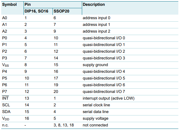
| Pin Diagram |
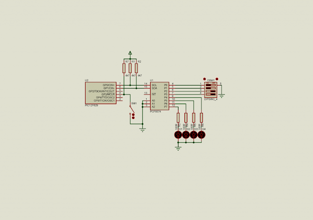
In this example, I read data from the lower nibble of PCF8574 input and output to its higher nibble to the port.
 |
| Schematic Diagram |
Source Code.
#include<12F629.h>
/*Use internal RC oscillator*/
#fuses INTRC_IO
#use delay(clock=4M)
/*implementing the software-base I2C*/
#use i2c(scl=pin_a0,sda=pin_a1,FORCE_SW)

void main(void){
   char rcvData=0;

   while(1){
      /*Turn on lower nibble high
      for digital input*/
      i2c_start();
      i2c_write(0x40);
      i2c_write(rcvData|0x0F);
      i2c_stop();

      /*Read the input state of
      lower nibble*/
      i2c_start();
      i2c_write(0x41);
      rcvData=i2c_read();
      i2c_stop();

      /*Shift the inputs right
      to the output*/
      rcvData<<=4;

      /*Write Data to output*/
      i2c_start();
      i2c_write(0x40);
      i2c_write(0x0F);
      i2c_stop();

      /*Turn on lower nibble high
      for digital input*/
      i2c_start();
      i2c_write(0x40);
      i2c_write(rcvData|0x0F);
      i2c_stop();

      /*wait for 100 mS*/
      delay_ms(100);
   }
}
Click here to download the complete example. This example uses the ATMega32 to interfaces with the PCF8574A using its TWI module.
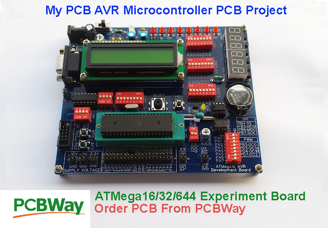
If you want a standard PCB for ATMega32 micro-controller, you can order my AVR Microcontroller project from PCBWay with a reasonable price. Click here to get a free $5 credit for new account.
 |
| ATMega16 ATMega32 Experiment Board PCB from PCBWay |


No comments:
Post a Comment