Overview Of DS1307 I2C RTC
A real time clock (RTC) device creates current date and time. A precise oscillator synchronizes the timing of the RTC. A back up battery, typically a CR-2032 coin battery keeps the RTC alive when the system power supply is turned off.
|
Simulating Circuit For This Example |

An RTC usually an external IC with SPI or I2C interface. An I2C interface has an advantage of using only two wires on a single bus, while an RTC with SPI interface requires more than two wires.
Maxim DS1307 is an RTC with I2C interface. It’s an 8-pin integrated circuit. It’s package has two options SO and PDIP. PDIP package is very useful in prototyping.
|
A piece of DS1307 I stock. |

|
Pin diagram from device's datasheet |

Each pin has their own name and functioning as lists below.
- X1 – Crystal connection pin 1 : It’s connects to one pin of a 32.768kHz Quartz Crystal. It must by-pass a 12.5pF capacitor to the ground.
- X2 – Crystal connection pin 2: It’s connects to one other pin of the 32.768kHz Quartz Crystal. It also require a by-pass capacitor.
- VBAT – Backup supply input : It’s the positive pin of the backup battery, usually a 3V coin battery.
- GND – Ground
- SDA – Serial Data Input/Output : This data pin needs a pull-up resistor.
- SCL – Serial Clock Input : This clock pin accepts clock pulse from the master I2C device. It also requires a pull-up resistor.
- SQW/OUT- Square wave/output driver : This output pin generates an output square wave between 1 Hz to 32 kHz by software control.
- VCC – Positive power supply – It work at typically +5 V DC.
The connection diagram to the microcontroller is shown below.
|
Typical circuit connection to MCU |

Since the communication pins SCL(Serial Clock) and SDA(Serial Data) are open-drain, they require its own pull-up resistor, respectively. The resistance of the pull-up resistor is between 4.7 kOhm to 10 kOhm. For higher data rate we use a lower resistance.
Date and time data store in time-keeper registers. Each register is 8-bit wide with 64 rows.
|
RAM Registers From device's datasheet |

From the address 0x00 to 0x06 are time registers. The 0x07 register is the control register. The remaining registers are RAM space.
The control register control the operation of SQW/OUT pin.
|
Control Register |

Control register functions:
- Bit 7 : OUT : This bit control the output level of SQW/OUT pin.
- Bit 4 : SQWE (Square-wave Enable) : Setting this bit to ‘1’ allowing the output wave from SQW/OUT pin.
- Bit 1 and Bit 0 are rate select bits
|
SQW rate selection bits |

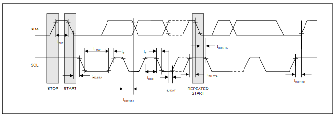
I do not list the details of I2C protocol here because there are a lot of resources on the web. The fundamental timing of the SDA and SCL pin list below.
|
I2C Timing Diagram |
Writing to I2C device commonly send the address and send data. Reading from it means getting the data from the sent address.
|
Writing to DS1307 |

|
Reading from DS1307 |

The DS1307 write address is 0xD0 while the reading address is 0xD1.
Programming And Interfacing
Most microcontrollers shipped with I2C, allowing an easy interfacing to this device. But whenever any selected microcontroller has an absence of I2C, we must write a software-base I2C in any assembler or compiler.
CCS PICC compiler is a embedded C compiler targeting 8-bit and 16-bit PIC devices. It has a ready-to-use C function for I2C. Any device device with I2C, we can use a fast and robust hardware I2C library. However, for any device without I2C we must use a software I2C library with a select-able pins.
In this example, I use PIC16F716 in my closet. However, this PICMicro doesn’t have I2C module in its peripherals. I use software I2C library in the compiler. It’s fast and reliable.
|
PIC16F716-I/P 18-Pin DIP I use for my prototyping. |

Data and time are read from ds1307 and display them on the 20×2 character LCD.
CCS PICC source code lists below.
#include<16F716.h>
#fuses HS
#use delay(clock=20M)
#define Device_SDA PIN_A0
#define Device_SCL  PIN_A1
#use i2c(FORCE_SW,sda=Device_SDA, scl=Device_SCL)
#define LCD_RS_PIN      PIN_B1
#define LCD_RW_PIN      PIN_B2
#define LCD_ENABLE_PIN  PIN_B3
#define LCD_DATA4       PIN_B4
#define LCD_DATA5       PIN_B5
#define LCD_DATA6       PIN_B6
#define LCD_DATA7       PIN_B7
#include <lcd.c>
char myDay[8];
void dayOfWeek(char _day){
   switch(_day){
      case 1: myDay="Sunday";    break;
      case 2: myDay="Monday";    break;
      case 3: myDay="Tuesday";   break;
      case 4: myDay="Wednesday"; break;
      case 5: myDay="Thursday";  break;
      case 6: myDay="Friday";    break;
      case 7: myDay="Saturday";  break;
   }
}
void rtcControl(char address,char control){
   i2c_start();
   i2c_write(0xD0);
   i2c_write(address);
   i2c_write(control);
   i2c_stop();
}
char rtcGet(char address){
   char dataRam;
   i2c_start();
   i2c_write(0xD0);
   i2c_write(address);
   i2c_stop();

   i2c_start();
   i2c_write(0xD1);
   dataRam=i2c_read(FALSE);
   i2c_stop();

   return dataRam;
}
void main(){

   char s,m,h;
   char _day,_date,_month,_years;
   /*Disable analog inputs*/
   setup_adc_ports(NO_ANALOGS);
   lcd_init();
   /*Enable 1 second output pin*/
   rtcControl(0x07,0x10);


   while(1){
      s=rtcGet(0x00);
      m=rtcGet(0x01);
      h=rtcGet(0x02);
      _day=rtcGet(0x03);
      _date=rtcGet(0x04);
      _month=rtcGet(0x05);
      _years=rtcGet(0x06);
      /*get day of week in string format*/
      dayOfWeek(_day);
      lcd_gotoxy(1,1);
      printf(LCD_PUTC,"%x:%x:%x %s",h,m,s,myDay);
      lcd_gotoxy(1,2);
      printf(LCD_PUTC,"%x/%x/20%x",_month,_day,_years);
      delay_ms(1000);
   }
}
 |
| Schematic Diagram |
Sungguh Artikel Yang Sangat Menginspirasi, terima kasih.
ReplyDeleteSalam Kenal ya dari IDProperti - Pasang Iklan Properti