Microchip MCP3204
MCP3204 is a 12-bit analog to digital converter (ADC). It's a discrete ADC IC with serial peripheral interface (SPI). There are four analog input channels, with two reference voltage pins. Using a 5 V supply voltage, the ADC conversion rate takes up to 100 ksps.
 |
| A simulating program. |
For more numbers of analog input channel, MCP3408 has up to 8 analog input channel with the same functionalities.
|
A sample of MCP3204 from the device's vendor |

|
Pin diagram |

Both MCP3204 and MCP3208 come with DIP package and SMD package. MCP3204 is a 14-pin DIP or TSSOP package. Each pin function lists below.
|
MCP3204 pin function table from the device's datasheet |

The 12-bit ADC creates a digital value of 4096 in decimal. We can find the digital equivalent to analog voltage as follow.
|
Digital output code for 12-bit ADC |

SPI communication initiated by pulling the CS pin low. Data is shift out and in as below.
|
SPI communication with MCP3204 |

The first four bits of DIN are configuration bits for MCP3204/MCP3206. Setting these four bits could make varieties of ADC reading.
|
Configuration bits for the MCP3204 |
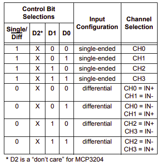
ADC reading could be a single-ended mode or a differential-pair mode, IN- and IN+.
CCS PICC Interfacing And Programming Using MCP3204 driver
PIC16F84A doesn't come with hardware SPI peripheral. However, using CCS PICC compiler interfacing with this device accomplished by software SPI library and the driver for MCP3204. A driver mcp3294.c is ready to use with some functions.
- adc_init() - call after the power up
- value = read_analog_mcp( channel, mode ) - read analog channel (0 to 3), when mode = 0 it read in differential mode otherwise single-ended mode.
- value = read_analog( channel ) - read analog channel (0 to 7) in single-ended mode.
- convert_to_volts( value, string ) - read analog value with equivalent analog voltage, and convert it to string "0.000".
In this example, I use this ADC to read four analog inputs channel in single-ended mode. These four values display on a character LCD.
|
Schematic Diagram |

The overall program consumes 81% of the flash memory in PIC16F84A.
|
Statistics of this program |

A took a screen shot of this program from the simulator.
|
| A simulating program. |
No comments:
Post a Comment