Saturday, September 16, 2023

STM32F103C8T6 Blue Pill And Character LCD Interfacing In 4-Bit Mode Example

In previous post, I showed about the LCD interfacing in 4-bit mode. The HD44780 allow the micro-processor to send the 8-bit data or command using an 4-bit interfacing. This process requires the microprocessor to send the 8-bit command or data twice over the 4-bit wire. The microprocessor send the higher nibble D4...D7 first, and then the lower nibble D0...D3. This technique saves the number of microprocessor digital output pins and circuit wiring. For more information about 4-bit LCD interfacing you can read this article.

STM32F103C8T6 Blue Pill And Character LCD Interfacing In 4-Bit Mode Example
Circuit Wiring On Bread Board


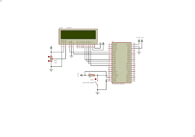
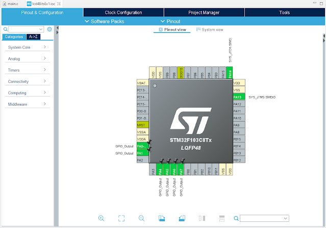
In this programming example, I use the lower byte of Port A. It's 16-bit wide. Where the LCD connections between the STM32F103C8R6 Blue Pill are,

  • LCD Register Select (RS) connects to PA0,
  • LCD Read or Write (R/W) connects to GND as the LCD just need to receive command or data,
  • LCD Enable (EN) connects to PA1,
  • LCD Data D0...D3 left unconnected or connects GND, while the LCD Data D4...D7 connects to the Blue Pill PA4...PA7.

STM32CubeIDE Code Configuration Wizard allows the programmer to select any peripherals and system settings without writing code in C/C++ source file.

STM32F103C8T6 Blue Pill And Character LCD Interfacing In 4-Bit Mode Example

GPIO Selection

In SYS tab I selected Serial Wire as its Debug interface. The System Wake-Up must left uncheck allowing PA0 as digital I/O.

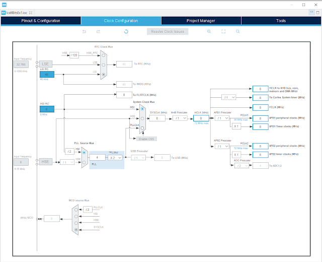
I use its 8MHz HSI RC as the clock source (internal). There is no pre-scaling or post scaling of this clock source.

STM32F103C8T6 Blue Pill And Character LCD Interfacing In 4-Bit Mode Example

Clock Configuration

The schematic below uses a modified model of the Blue Pill in Proteus original library. It also able to simulate.

STM32F103C8T6 Blue Pill And Character LCD Interfacing In 4-Bit Mode Example
Schematic
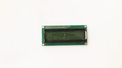
The LCD module is low cost JHD16 that cost around 1USD.
 

STM32F103C8T6 Blue Pill And Character LCD Interfacing In 4-Bit Mode Example

JHD16 LCD Module Front


STM32F103C8T6 Blue Pill And Character LCD Interfacing In 4-Bit Mode Example

JHD16 LCD Module Back

The source source code is quite easy as it's similar to LCD interfacing in 8-bit mode.

  1. /* USER CODE BEGIN Header */
  2. /**
  3.   ******************************************************************************
  4.   * @file : main.c
  5.   * @brief : Main program body
  6.   ******************************************************************************
  7.   * @attention
  8.   *
  9.   * <h2><center>&copy; Copyright (c) 2023 STMicroelectronics.
  10.   * All rights reserved.</center></h2>
  11.   *
  12.   * This software component is licensed by ST under BSD 3-Clause license,
  13.   * the "License"; You may not use this file except in compliance with the
  14.   * License. You may obtain a copy of the License at:
  15.   * opensource.org/licenses/BSD-3-Clause
  16.   *
  17.   ******************************************************************************
  18.   */
  19. /* USER CODE END Header */
  20. /* Includes ------------------------------------------------------------------*/
  21. #include "main.h"
  22.  
  23. /* Private function prototypes -----------------------------------------------*/
  24. void SystemClock_Config(void);
  25. static void MX_GPIO_Init(void);
  26.  
  27. /**
  28.   * @brief The application entry point.
  29.   * @retval int
  30.   */
  31.  
  32. #define DPORT GPIOA->ODR
  33.  
  34. void delay1(uint16_t dTime){
  35. for(uint16_t i=0;i<dTime;i++);
  36. }
  37.  
  38. void delay2(uint8_t dTime){
  39. for(uint8_t i=0;i<dTime;i++) delay1(5000);
  40. }
  41.  
  42. void lcdCmd(uint8_t cmd){
  43. uint8_t temp=0x02;
  44. DPORT=temp|(cmd&0xF0);
  45. delay1(100);
  46. temp=0;
  47. DPORT=temp|(cmd&0xF0);
  48. delay1(1000);
  49.  
  50. temp=0x02;
  51. DPORT=temp|(cmd<<4);
  52. delay1(100);
  53. temp=0;
  54. DPORT=temp|(cmd<<4);
  55. }
  56.  
  57. void lcdDat(uint8_t dat){
  58. uint8_t temp=0x03;
  59. DPORT=temp|(dat&0xF0);
  60. delay1(100);
  61. temp=0x01;
  62. DPORT=temp|(dat&0xF0);
  63. delay1(1000);
  64.  
  65. temp=0x03;
  66. DPORT=temp|(dat<<4);
  67. delay1(100);
  68. temp=0x01;
  69. DPORT=temp|(dat<<4);
  70. }
  71.  
  72. void lcdInit(void){
  73. DPORT=0x00;
  74. delay1(2000);
  75. lcdCmd(0x33);
  76. delay1(100);
  77. lcdCmd(0x32);
  78. delay1(100);
  79. lcdCmd(0x28);
  80. delay1(100);
  81. lcdCmd(0x0F);
  82. delay1(100);
  83. lcdCmd(0x01);
  84. delay1(2000);
  85. lcdCmd(0x06);
  86. delay1(100);
  87. }
  88.  
  89. void lcdStr(uint8_t *str){
  90. while(*str) lcdDat(*str++);
  91. }
  92.  
  93. void lcdXY(uint8_t x,uint8_t y){
  94. // 16x2 LCD
  95. uint8_t tbe[2]={0x80,0xC0};
  96. // 20x4 LCD
  97. //uint8_t tbe[]={0x80,0xC0,0x94,0xD4};
  98. lcdCmd(tbe[y-1]+x-1);
  99. delay1(100);
  100. }
  101.  
  102. void lcdClear(void){
  103. lcdCmd(0x01);
  104. delay1(100);
  105. }
  106.  
  107. int main(void)
  108. {
  109. /* Reset of all peripherals, Initializes the Flash interface and the Systick. */
  110. HAL_Init();
  111.  
  112. /* Configure the system clock */
  113. SystemClock_Config();
  114.  
  115. /* Initialize all configured peripherals */
  116. MX_GPIO_Init();
  117.  
  118. lcdInit();
  119. lcdClear();
  120. delay2(100);
  121.  
  122. lcdXY(2,1);
  123. lcdStr("STM32F103C8T6");
  124. delay2(100);
  125. lcdXY(1,2);
  126. lcdStr("4-Bit Mode LCD");
  127. /* Infinite loop */
  128. /* USER CODE BEGIN WHILE */
  129. while (1)
  130. {
  131. /* USER CODE END WHILE */
  132.  
  133. /* USER CODE BEGIN 3 */
  134. }
  135. /* USER CODE END 3 */
  136. }
  137.  
  138. /**
  139.   * @brief System Clock Configuration
  140.   * @retval None
  141.   */
  142. void SystemClock_Config(void)
  143. {
  144. RCC_OscInitTypeDef RCC_OscInitStruct = {0};
  145. RCC_ClkInitTypeDef RCC_ClkInitStruct = {0};
  146.  
  147. /** Initializes the RCC Oscillators according to the specified parameters
  148.   * in the RCC_OscInitTypeDef structure.
  149.   */
  150. RCC_OscInitStruct.OscillatorType = RCC_OSCILLATORTYPE_HSI;
  151. RCC_OscInitStruct.HSIState = RCC_HSI_ON;
  152. RCC_OscInitStruct.HSICalibrationValue = RCC_HSICALIBRATION_DEFAULT;
  153. RCC_OscInitStruct.PLL.PLLState = RCC_PLL_NONE;
  154. if (HAL_RCC_OscConfig(&RCC_OscInitStruct) != HAL_OK)
  155. {
  156. Error_Handler();
  157. }
  158. /** Initializes the CPU, AHB and APB buses clocks
  159.   */
  160. RCC_ClkInitStruct.ClockType = RCC_CLOCKTYPE_HCLK|RCC_CLOCKTYPE_SYSCLK
  161. |RCC_CLOCKTYPE_PCLK1|RCC_CLOCKTYPE_PCLK2;
  162. RCC_ClkInitStruct.SYSCLKSource = RCC_SYSCLKSOURCE_HSI;
  163. RCC_ClkInitStruct.AHBCLKDivider = RCC_SYSCLK_DIV1;
  164. RCC_ClkInitStruct.APB1CLKDivider = RCC_HCLK_DIV1;
  165. RCC_ClkInitStruct.APB2CLKDivider = RCC_HCLK_DIV1;
  166.  
  167. if (HAL_RCC_ClockConfig(&RCC_ClkInitStruct, FLASH_LATENCY_0) != HAL_OK)
  168. {
  169. Error_Handler();
  170. }
  171. }
  172.  
  173. /**
  174.   * @brief GPIO Initialization Function
  175.   * @param None
  176.   * @retval None
  177.   */
  178. static void MX_GPIO_Init(void)
  179. {
  180. GPIO_InitTypeDef GPIO_InitStruct = {0};
  181.  
  182. /* GPIO Ports Clock Enable */
  183. __HAL_RCC_GPIOA_CLK_ENABLE();
  184.  
  185. /*Configure GPIO pin Output Level */
  186. HAL_GPIO_WritePin(GPIOA, GPIO_PIN_0|GPIO_PIN_1|GPIO_PIN_4|GPIO_PIN_5
  187. |GPIO_PIN_6|GPIO_PIN_7, GPIO_PIN_RESET);
  188.  
  189. /*Configure GPIO pins : PA0 PA1 PA4 PA5
  190.   PA6 PA7 */
  191. GPIO_InitStruct.Pin = GPIO_PIN_0|GPIO_PIN_1|GPIO_PIN_4|GPIO_PIN_5
  192. |GPIO_PIN_6|GPIO_PIN_7;
  193. GPIO_InitStruct.Mode = GPIO_MODE_OUTPUT_PP;
  194. GPIO_InitStruct.Pull = GPIO_NOPULL;
  195. GPIO_InitStruct.Speed = GPIO_SPEED_FREQ_LOW;
  196. HAL_GPIO_Init(GPIOA, &GPIO_InitStruct);
  197.  
  198. }
  199.  
  200. /**
  201.   * @brief This function is executed in case of error occurrence.
  202.   * @retval None
  203.   */
  204. void Error_Handler(void)
  205. {
  206. /* USER CODE BEGIN Error_Handler_Debug */
  207. /* User can add his own implementation to report the HAL error return state */
  208. __disable_irq();
  209. while (1)
  210. {
  211. }
  212. /* USER CODE END Error_Handler_Debug */
  213. }
  214.  
  215. #ifdef USE_FULL_ASSERT
  216. /**
  217.   * @brief Reports the name of the source file and the source line number
  218.   * where the assert_param error has occurred.
  219.   * @param file: pointer to the source file name
  220.   * @param line: assert_param error line source number
  221.   * @retval None
  222.   */
  223. void assert_failed(uint8_t *file, uint32_t line)
  224. {
  225. /* USER CODE BEGIN 6 */
  226. /* User can add his own implementation to report the file name and line number,
  227.   ex: printf("Wrong parameters value: file %s on line %d\r\n", file, line) */
  228. /* USER CODE END 6 */
  229. }
  230. #endif /* USE_FULL_ASSERT */
  231.  
  232. /************************ (C) COPYRIGHT STMicroelectronics *****END OF FILE****/
  233.  

I use C/C++ loop to create delay without using the STM32CubeIDE Hal_Delay function. However the delay time is not known.
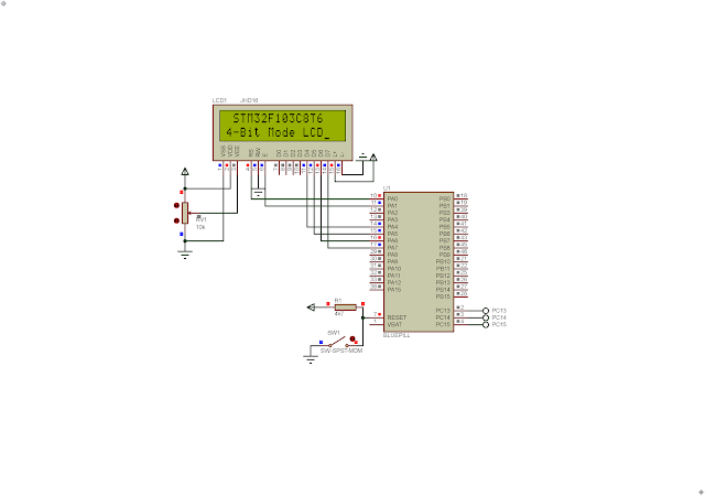
STM32F103C8T6 Blue Pill And Character LCD Interfacing In 4-Bit Mode Example
Simulating Program In Proteus

 Click here to download its source file.


No comments:

Post a Comment

Search This Blog

Labels

25AA010A (1) 8051 (7) 93AA46B (1) ADC (30) Analog Comparator (1) Arduino (15) ARM (6) AT89C52 (7) ATMega32 (54) AVR (57) CCS PICC (28) DAC (1) DHT11 (2) Display (105) Distance Sensor (3) DS18B20 (3) dsPIC (2) dsPIC30F1010 (2) EEPROM (5) Environment Sensor (4) esp8266 (1) I2C (29) Input/Output (67) Interrupt (19) Keil (5) Keypad (10) LCD (46) Master/Slave (1) MAX7221 (1) MCP23017 (5) MCP23S17 (4) Meter (3) MikroC (2) Motor (15) MPLABX (66) Nokia 5110 LCD (3) OLED (2) One-Wire (6) Oscillator (8) PCB (6) PCD8544 (3) PCF8574 (5) PIC (107) PIC12F (2) PIC16F628A (2) PIC16F630 (1) PIC16F716 (3) PIC16F818 (10) PIC16F818/819 (2) PIC16F84A (15) PIC16F876A (1) PIC16F877A (9) PIC16F88 (1) PIC16F887 (60) PIC18 (19) PIC18F1220 (4) PIC18F2550 (3) PIC18F4550 (12) PWM (11) RTC (8) Sensor (10) SH1106 (1) Shift Register (11) Shift Registers (2) SPI (24) STM32 (6) STM32 Blue Pill (6) STM32CubeIDE (6) STM32F103C8T6 (6) SysTick (3) temperature sensor (11) Thermometer (21) Timer/Counter (30) TM1637 (2) UART (7) Ultrasonic (4) Voltmeter (7) WDT (1) XC16 (2) XC8 (94)