Overview
In the previous post, I showed a 8-bit parallel port LCD interfacing with ATMega32 digital ports. However, as it's stated in the datasheet of HD44780, this controller could interface using only its four upper data bits (D4 to D7).
00:00 / 00:00
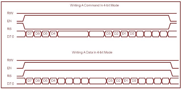
In 4-bit data transfer mode, however the controller requires its full 8-bit instruction or LCD data. To send the 8-bit instruction or data, the connected MCU needs to send it twice.
- The MCU sends the high nibble first
- Finally the lower nibble shift left for four times and send it to the LCD D7:4 pins.
![]() |
Timing diagram for 4-bit interfacing mode |
By following, the JHD162A the step-by-step 4-bit LCD interfacing configuration shown below.
LCD Interfacing And Programming In 4-bit Mode
Using Two Distinct Ports
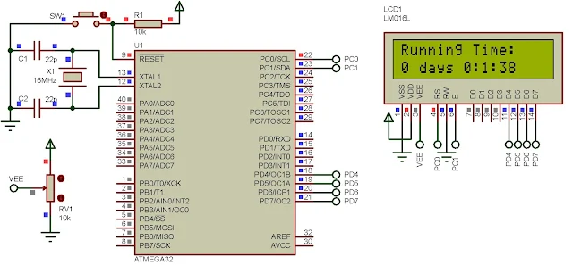
At this beginning example, I use two distinct port for LCD control pins and LCD data/instruction pins, respectively.
![]() |
Schematic diagram for 4-bit LCD interfacing |
The program display the time in days and HH:MM:SS since the MCU powered up. I fetch the source code from my GitHub gist respiratory below.
This file contains bidirectional Unicode text that may be interpreted or compiled differently than what appears below. To review, open the file in an editor that reveals hidden Unicode characters.
Learn more about bidirectional Unicode characters
/* | |
* main.c | |
* | |
* Created: 8/31/2020 8:57:06 AM | |
* Author : aki-technical | |
*/ | |
#include <avr/io.h> | |
#include <stdio.h> | |
#define F_CPU 16000000UL | |
#include <util/delay.h> | |
#define lcdControl PORTC | |
#define lcdData PORTD | |
#define controlDir DDRC | |
#define dataDir DDRD | |
#define RS 0 | |
#define EN 1 | |
void lcdPortInit(void){ | |
/*PORTC and PORTD Are Output To LCD*/ | |
controlDir=0xFF; | |
dataDir=0xFF; | |
} | |
void writeCommand(char command){ | |
//Set RS to 0 | |
lcdControl&=~(1<<RS); | |
//Set EN to 1 to latch data | |
lcdControl|=(1<<EN); | |
//Put MSB Of The Command | |
lcdData=command; | |
//Clear EN to finish | |
lcdControl&=~(1<<EN); | |
_delay_us(50); | |
//Set EN to 1 to latch data | |
lcdControl|=(1<<EN); | |
//Put LSB Of The Command | |
lcdData=command<<4; | |
//Clear EN to finish | |
lcdControl&=~(1<<EN); | |
_delay_ms(3); | |
} | |
void writeChararacter(char character){ | |
//Set RS to 1 | |
lcdControl|=(1<<RS); | |
//Set EN to 1 to latch data | |
lcdControl|=(1<<EN); | |
//Put MSB Of The Character | |
lcdData=character; | |
//Clear EN to finish | |
lcdControl&=~(1<<EN); | |
_delay_us(50); | |
//Set EN to 1 to latch data | |
lcdControl|=(1<<EN); | |
//Put LSB Of The Character | |
lcdData=character<<4; | |
//Clear EN to finish | |
lcdControl&=~(1<<EN); | |
_delay_ms(3); | |
} | |
void writeString(char *text){ | |
while(*text) writeChararacter(*text++); | |
} | |
/*This function ease of setting the cursor position*/ | |
void setXy(int x,int y){ | |
char numberOfLines[2]={0x80,0xC0}; | |
/* The position starts from (x,y)=(0,0) */ | |
writeCommand(numberOfLines[x]+y); | |
} | |
int main(void) | |
{ | |
char cnt[16]=""; | |
char dayCnt=0,secondCnt=0,minuteCnt=0,hourCnt=0; | |
/*Initialize the LCD PORT*/ | |
lcdPortInit(); | |
/*Writing the instructions | |
4-bit mode, 2-line,5x8 dot*/ | |
writeCommand(0b00110011); | |
writeCommand(0b00110010); | |
writeCommand(0b00101000); | |
writeCommand(0x01); | |
/*Turn On Display, Cursor Off*/ | |
writeCommand(0b00001100); | |
/*Cursor Shift in Increment Mode*/ | |
writeCommand(0b00000110); | |
while (1) | |
{ | |
secondCnt++; | |
if(secondCnt>=60){ | |
secondCnt=0; | |
minuteCnt++; | |
} | |
if (minuteCnt>=60) | |
{ | |
minuteCnt=0; | |
hourCnt++; | |
} | |
if (hourCnt>=24) | |
{ | |
hourCnt=0; | |
minuteCnt=0; | |
secondCnt=0; | |
} | |
//Convert timeCnt to String | |
sprintf(cnt,"%d days %d:%d:%d ",dayCnt,hourCnt,minuteCnt,secondCnt); | |
//Select the upper right | |
setXy(0,0); | |
/*Writing the text to the display*/ | |
writeString("Running Time:"); | |
/*Select Second Line*/ | |
setXy(1,0); | |
writeString(cnt); | |
_delay_ms(1000); | |
} | |
} |
![]() |
The simulation shows 1 minute and 38 seconds since the MCU powered up. |
Click here to download this example archive.
Using A Single Port
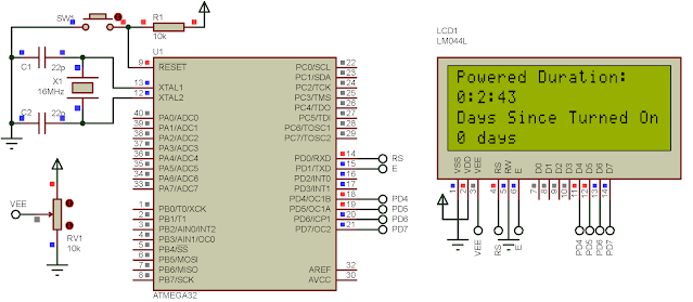
We can use a single port for LCD interfacing in some situations. The overall process is the same. But we must select any control pins in the same port.
![]() |
Using A Single Port - Here I use a 20x4 LCD. |
Source code fetched from gist.
This file contains bidirectional Unicode text that may be interpreted or compiled differently than what appears below. To review, open the file in an editor that reveals hidden Unicode characters.
Learn more about bidirectional Unicode characters
/* | |
* hd44780_4bit_Example_2.c | |
* | |
* Created: 8/31/2020 7:06:47 PM | |
* Author : aki-technical | |
*/ | |
#include <avr/io.h> | |
#include <stdio.h> | |
#define F_CPU 16000000UL | |
#include <util/delay.h> | |
#define lcdPort PORTD | |
#define lcdDir DDRD | |
#define RS 0 | |
#define E 1 | |
void lcdPortInit(void){ | |
//Only PORTD Is LCD Port | |
lcdDir=0xFF; | |
} | |
void writeCommand(char command){ | |
lcdPort=(command&0xF0)|(1<<E); | |
lcdPort=(command&0xF0); | |
_delay_us(50); | |
lcdPort=(command<<4)|(1<<E); | |
lcdPort=(command<<4); | |
_delay_ms(3); | |
} | |
void writeChararacter(char character){ | |
lcdPort=(character&0xF0)|(1<<E)|(1<<RS); | |
lcdPort=(character&0xF0)|(1<<RS); | |
_delay_us(50); | |
lcdPort=(character<<4)|(1<<E)|(1<<RS); | |
lcdPort=(character<<4)|(1<<RS); | |
_delay_ms(3); | |
} | |
void writeString(char *text){ | |
while(*text) writeChararacter(*text++); | |
} | |
/*This function ease of setting the cursor position*/ | |
void setXy(int x,int y){ | |
/*Select A 40x4 LCD*/ | |
char numberOfLines[4]={0x80,0xC0,0x94,0xD4}; | |
/* The position starts from (x,y)=(0,0) */ | |
writeCommand(numberOfLines[x]+y); | |
} | |
int main(void) | |
{ | |
char cnt[8]; | |
char dayCnt=0,secondCnt=0,minuteCnt=0,hourCnt=0; | |
/*Initialize the LCD PORT*/ | |
lcdPortInit(); | |
/*Writing the instructions | |
4-bit mode, 2-line,5x8 dot*/ | |
writeCommand(0b00110011); | |
writeCommand(0b00110010); | |
writeCommand(0b00101000); | |
writeCommand(0x01); | |
/*Turn On Display, Cursor Off*/ | |
writeCommand(0b00001100); | |
/*Cursor Shift in Increment Mode*/ | |
writeCommand(0b00000110); | |
while (1) | |
{ | |
secondCnt++; | |
if(secondCnt>=60){ | |
secondCnt=0; | |
minuteCnt++; | |
} | |
if (minuteCnt>=60) | |
{ | |
minuteCnt=0; | |
hourCnt++; | |
} | |
if (hourCnt>=24) | |
{ | |
hourCnt=0; | |
minuteCnt=0; | |
secondCnt=0; | |
} | |
//Convert HH:MM:SS To String | |
sprintf(cnt,"%d:%d:%d ",hourCnt,minuteCnt,secondCnt); | |
//Select the upper right | |
setXy(0,0); | |
/*Writing the time to LCD*/ | |
writeString("Powered Duration:"); | |
/*Select Second Line*/ | |
setXy(1,0); | |
writeString(cnt); | |
/*Convert days count to string*/ | |
sprintf(cnt,"%d days",dayCnt); | |
/*Select Third Line*/ | |
setXy(2,0); | |
writeString("Days Since Turned On:"); | |
/*Select Forth Line*/ | |
setXy(3,0); | |
writeString(cnt); | |
_delay_ms(1000); | |
} | |
} |
![]() |
Schematic Diagram For A Single Port Interfacing |
Click here to download example archive. This character LCD can be driven by a serial to parallel shift registers. We can use these two chips - the SN74HC595 and the SN74HC164.
No comments:
Post a Comment