The PCF8574 series is popular among Arduino users especially the character LCD driving. Its output port is 8-bit bi-directional. So we can use this chip to make a 4x4 matrix keypad. The microprocessor uses only two pins (SDA and SCL) via its I2C communication module to interface with this serial matrix keypad.
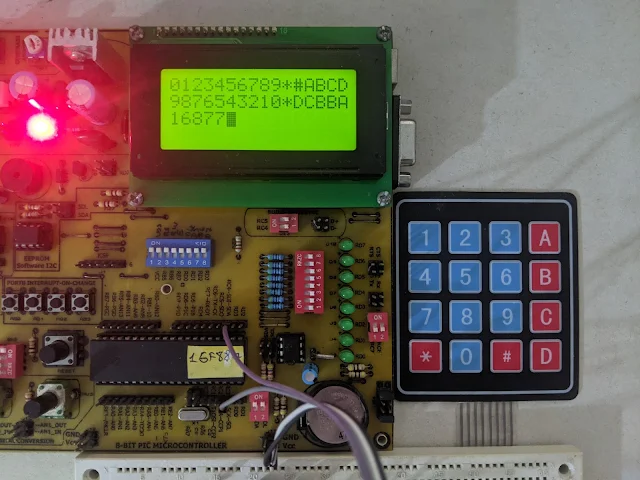 |
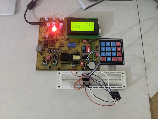
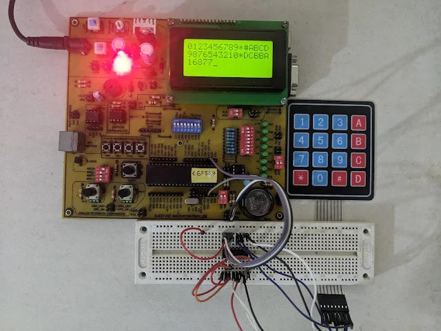
| Hardware Experiment on PIC16F887 Prototype Board |
I use a 4x4 membrane keypad module for Arduino. It's low cost that we doesn't need to make our own PCB.
%20Pin%20Out.jpg) |
| 16 Key Membrane Switch Keypad 4X4 3X4 Matrix Keyboard For Arduino Diy Kit |
The I2C slave address of PCF8574AP (DIP-16) is 0x70 (write) and 0x71 (read) when A2...A0 are wired to GND.
.jpg) |
| PCF8574AP 16-Pin DIP |
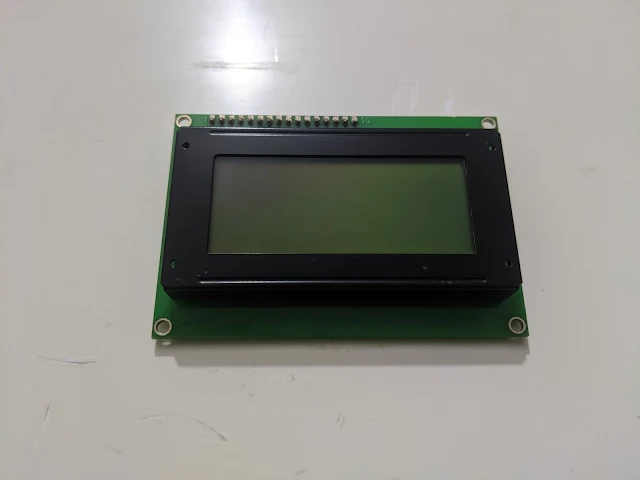
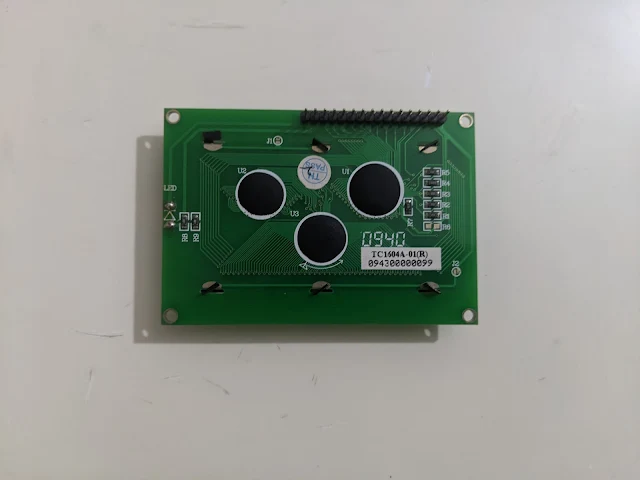
I use the on-board TinSharp TC1604A-01 16x4 character LCD module I posses.
I use the 4-bit data transfer mode to save the I/O pins of micro-controller.
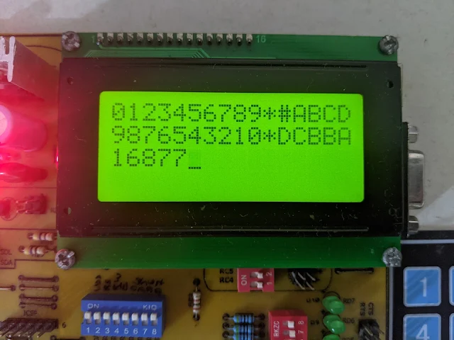
Using the MPLABX IDE and its XC8 C compiler is pretty easy. Generated firmware is light-weight comparable the Assembly language. This program keep scanning the key press. Key value will show on the character LCD. The display is auto make a new line when ever the character counts reach 16. The the display is full it will clear the display and return home.
Click here to download this example from GitHub. I use Proteus to draw its schematic.
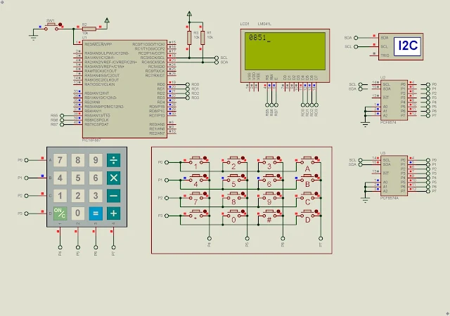 |
| Program Simulation |
Proteus simulation will work at slow speed due to custom firmware simulation. Using the prototype board, the firmware operation works very well without error and slowness.
This DIY PCB has a 20MHz crystal oscillator. But the PIC16F887 has an internal 8MHz RC oscillator. So I left the XTAL1 and XTAL2 pin unconnected.
Keypad scanning runs very flexible without error on this PIC DIY prototype board.
If you use the PCF8574 you need to change its I2C slave address.
No comments:
Post a Comment