Overview
Creating a varied analog voltage output from an MCU require an analog voltage generator, PWM (pulse width modulation). Making a analog voltage PWM to work, the user needs to know about all relevant register configurations to set the frequency and duty cycle of PWM signal.
However, in a high level embedded language, creating a PWM signal output doesn't need a deep level of low level hardware/register configuration. With a few C functions, the PWM signal output from any MCU could be created in a few minutes.
CCS PICC Basic Pulse Width Modulation Programming
Without using any technical detail of PWM software setting, we can create a PWM output from scratch with this compiler. In this introductory example, I use only a few C code to program the PWM.
- #use PWM directive
- pwm_set_duty_percent()
- CCPx or PWMx - Select a CCP/PWM module
- FREQUENCY=x - Set the frequency of PWM signal
- PERIOD=x - Set the period of PWM signal
- DUTY=x - The default duty cycle is 50% if it's not set.
The pwm_set_duty_percent specifies the duty cycle of PWM output signal. The syntax is pwm_set_duty_percent(stream,value). Where stream is optional, and value is ranges from 0 to 1000. For example when value = 500, the PWM duty cycle is 50% and so on.
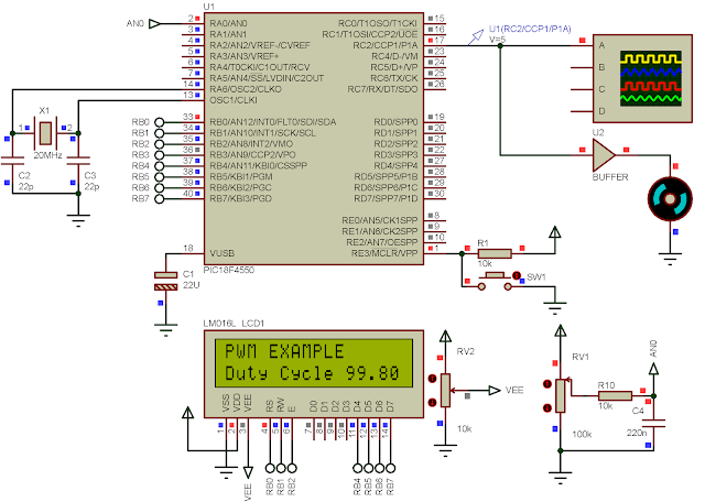
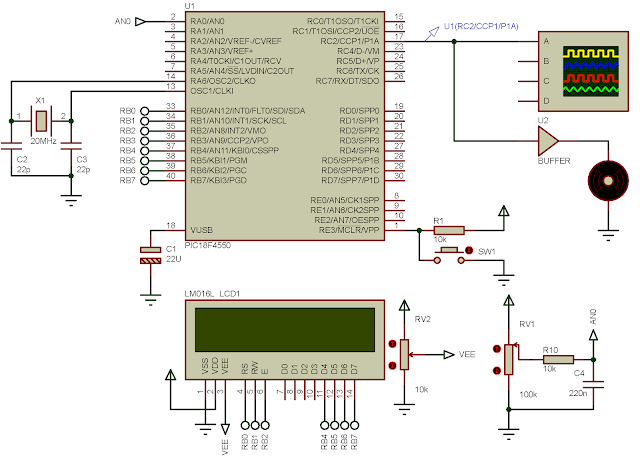
In this introductory example, I set a fixed frequency of PWM and a variable duty cycle. Duty cycle is adjusted by the variation of a POT. CCP1 is selected to make the PWM signal.
 |
| I adjust the POT to the MAX. |
C Source Code
Schematic
 |
| Schematic Diagram |
Click here to download this example in zip file.
No comments:
Post a Comment