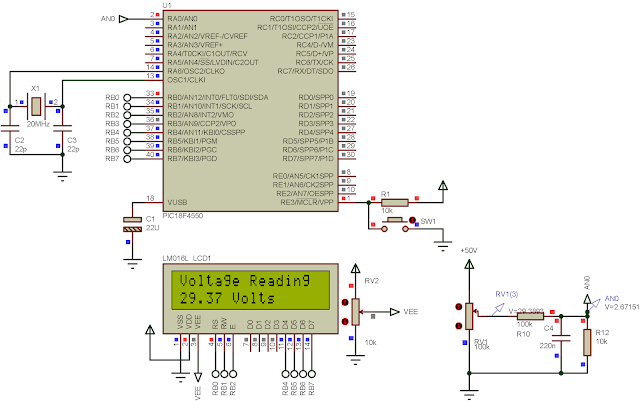
The ADC module of PIC18F4550 could read an analog input voltage up to 5 V DC with some DC offset. However, the outside analog voltage fed to the ADC could be greater than 5 V DC by adding a simple voltage divider circuit.
The voltage divider circuit is very simple, built by two resistors in this case. The output voltage from the divider circuit is smaller than the input according to the dividing factor. The factor created by picking up a different resistances of the selected's. The designer may decide and take a little math calculation using voltage divider theorem to get a specific division factor.
I don't show the overall process of math calculation here. You can see this post to get a full detail.
 |
| The MCU reads the analog input voltage fed to RA0. |
PICC Source Code
Schematic Diagram
 |
| Schematic Diagram |
Click here to download the zip file of this example.
If you want a standard PCB for ATMega32 micro-controller, you can order my AVR Microcontroller project from PCBWay with a reasonable price. Click here to get a free $5 credit for new account.
 |
| ATMega16 ATMega32 Experiment Board PCB from PCBWay |
Wow, I came to learn about Basic Series Digital Panel Meters, and your information is absolutely amazing! For more insights and if your are looking for the Top Basic Series Digital Panel Meters Manufacturer, check out Yokins! We specialize in reliable solutions to meet all your Digital Panel Meters. Keep up the great work!
ReplyDeleteVery great post. It's really very informative . After all I’ll be subscribing on your feed and I am hoping you write again very soon.And if you need more information aboutdigital panel meters Basic Series you can check out my page also. It will help you.
ReplyDeleteVery great post. It's really very informative . After all I’ll be subscribing on your feed and I am hoping you write again very soon.And if you need more information about digital panel meters basic series AC voltmeter you can check out my page also. It will help you.
ReplyDelete