Analog To Digital Converter (ADC) Module
The ADC module relates only with analog voltage value from any analog-output sensors or other analog circuits. Analog voltage value could be scaled to a smaller range value by using a two-resistor voltage divider circuit. For example a 50 V DC voltage could be scale to a range of lower than 5 V DC because the maximum analog reference voltage of ADC module of this device is +5 V DC.ADC Scaling Circuit Using Voltage Divider Rule
For the voltage divider of two resistor, I do a calculation as follow.
Using these two values of resistor, we could measure the analog voltage up to 50 V DC.
Program For Digital Voltmeter
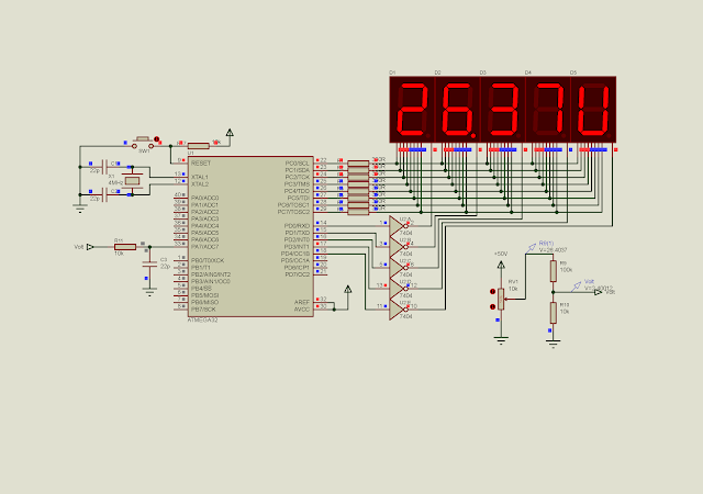
![]() |
A sample of program. The voltage reading is 26.37 Volts. |
Atmel Studio C source code. Click here to download source file.
This file contains bidirectional Unicode text that may be interpreted or compiled differently than what appears below. To review, open the file in an editor that reveals hidden Unicode characters.
Learn more about bidirectional Unicode characters
#include <avr/io.h> | |
#define F_CPU 4000000UL | |
#include <util/delay.h> | |
int adcResult; | |
void displayVoltage(){ | |
char ssd[10]={0x3F,0x06,0x5B,0x4F,0x66,0x6D,0x7D,0x07,0x7F,0x6F}; | |
float voltage; | |
unsigned int voltageDisplay; | |
/*make the input voltage with some error correction | |
the actual value is 0.09*/ | |
voltage=0.11*(adcResult*5)/1024; | |
/*convert the floating-point voltage to integer | |
for displaying*/ | |
voltageDisplay=(voltage*10000); | |
PORTD=0x00; | |
PORTC=ssd[voltageDisplay/1000]; | |
PORTD=0x01; | |
_delay_ms(10); | |
PORTD=0x00; | |
PORTC=ssd[(voltageDisplay%1000)/100]|0x80; | |
PORTD=0x02; | |
_delay_ms(10); | |
PORTD=0x00; | |
PORTC=ssd[(voltageDisplay%100)/10]; | |
PORTD=0x04; | |
_delay_ms(10); | |
PORTD=0x00; | |
PORTC=ssd[voltageDisplay%10]; | |
PORTD=0x08; | |
_delay_ms(10); | |
PORTD=0x00; | |
PORTC=0x3E; | |
PORTD=0x10; | |
_delay_ms(10); | |
} | |
int main(void) | |
{ | |
//PortC as output | |
DDRC=0xFF; | |
//PortD as output | |
DDRD=0xFF; | |
//PORTA is analog input | |
DDRA=0; | |
//Select AD7 | |
ADMUX|=0x07; | |
//Turn on the ADC module | |
ADCSRA|=(1<<ADEN); | |
while (1) | |
{ | |
//Start the conversion | |
ADCSRA|=(1<<ADSC); | |
//Wait for the completion | |
while((ADCSRA&(1<<ADSC))==1); | |
_delay_ms(25); | |
//Read the result | |
adcResult=ADCL+(ADCH<<8); | |
displayVoltage(); | |
} | |
} |
Schematic diagram is here.
Hello, please help me, I need an assembly code for this.
ReplyDeleteHi, I don't have Assembly code for this because I'm not good at Assembly language.
Delete