Sunday, May 24, 2020

Using timer 0 interrupt to create a PWM signal controlling a DC Motor

With the interrupt feature, we can create a fast PWM waveform. It produce a smother timing signal than using a pure delay function. But it is rougher than using a built-in PWM module of microcontroller.

Using timer 0 interrupt to create a PWM signal controlling a DC Motor
Schematic diagram. The CPU runs at 4 MHz. PC0 outputs a PWM signal to adjust the
speed of DC motor. PWM generated by a timer tick of timer 0 interrupt. SW3 decrease
the duty cycle of PWM. SW1 set the duty cycle to zero. SW2 increase the duty cycle,
speed up the DC motor.

In this example, I set the prescaler to 1:8. Since the CPU clock is 4 MHz, giving a 250 nano seconds period. With a 1:8 prescaler, timer 0 increase for every 8 x 250 nano seconds = 2 micro seconds.

At the timer 0 interrupt point, I want to trigger it at every 10 micro seconds. To get a 10 micro second timer tick, let (0.000010 second)/(0.000002 second) = 5. So, at the interrupt TCNT0 must be loaded with 256 - 5 = 251 or -5.

Source code's here.
#include <avr/io.h>
#include "avr/interrupt.h"
//A variable to count every 2 uS
unsigned int cnt=0;
unsigned char hTime=0;
#define speedUp (PIND&0x80)
#define stopPWM (PIND&0x40)
#define speedDw (PIND&0x20)
void myPWM(){
 if (speedUp==0)
 {
  if(hTime<95)
  hTime+=5;
  while(speedUp==0);
 }
 if (stopPWM==0)
 {
  hTime=0;
  while(stopPWM==0);
 }
  if (speedDw==0)
 {
  if(hTime>0) 
   hTime-=5;
  while(speedDw==0);
 }
 if (cnt<hTime)
 {   PORTC|=(1<<0);
 }
 else if(cnt>hTime){
  PORTC&=~(1<<0);
 }
 if(cnt>100) cnt=0;
}
int main(void)
{
 //Set PB0 to Output
 DDRC=0x01;
 //Clear PortC
 PORTC=0x00;
 //Set PD7, PD6 and PD5 to output
 DDRD=0x1F;
 //set PD7, PD6 and PD5 High
 PORTD=0xE0;
 //Set 1:8 pre-scaler
 TCCR0=0x02;
 //Clear overflow flag
 TIFR=0x01;
 //Enable Timer 0 interrupt
 TIMSK=0x01;
 //set global interrupt
 sei();
 while (1)
 {
  myPWM();
 }
}
ISR(TIMER0_OVF_vect){
 //Load -5 to make 10 uS interrupt time
 TCNT0=-5;
 cnt+=1;  TIFR=0x01;
}

I took a simulation screen shot.
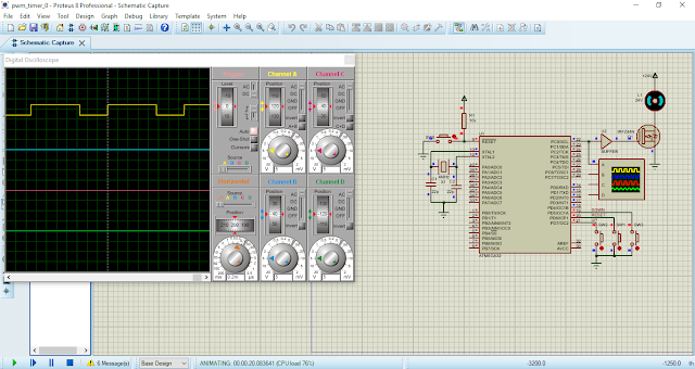
Using timer 0 interrupt to create a PWM signal controlling a DC Motor
A Simulation screen shot.
PC0 create a PWM signal output with a period 1.5 milli seconds.
The PWM frequency is 666 Hz. 

Back to main tutorial page ATMega32 tutorials in C with Atmel Studio 7.


No comments:

Post a Comment

Search This Blog

Labels

25AA010A (1) 8051 (7) 93AA46B (1) ADC (30) Analog Comparator (1) Arduino (15) ARM (6) AT89C52 (7) ATMega32 (56) AVR (57) CCS PICC (28) DAC (1) DHT11 (2) Display (105) Distance Sensor (3) DS18B20 (3) dsPIC (2) dsPIC30F1010 (2) EEPROM (5) Environment Sensor (4) esp8266 (1) I2C (29) Input/Output (67) Interrupt (19) Keil (5) Keypad (10) LCD (47) Master/Slave (1) MAX7221 (1) MCP23017 (5) MCP23S17 (4) Meter (3) MikroC (2) Motor (15) MPLABX (71) Nokia 5110 LCD (3) OLED (2) One-Wire (6) Oscillator (8) PCB (6) PCD8544 (3) PCF8574 (5) PIC (107) PIC12F (2) PIC16F628A (2) PIC16F630 (1) PIC16F716 (3) PIC16F818 (10) PIC16F818/819 (2) PIC16F84A (15) PIC16F876A (1) PIC16F877A (9) PIC16F88 (1) PIC16F887 (60) PIC18 (19) PIC18F1220 (4) PIC18F2550 (3) PIC18F4550 (12) PWM (11) RTC (8) Sensor (10) SH1106 (1) Shift Register (11) Shift Registers (3) SPI (24) STM32 (6) STM32 Blue Pill (6) STM32CubeIDE (6) STM32F103C8T6 (6) SysTick (3) temperature sensor (11) Thermometer (21) Timer/Counter (31) TM1637 (2) UART (7) Ultrasonic (4) Voltmeter (7) WDT (1) XC16 (2) XC8 (94)