MAX7221 SPI 8-Digit LED Display Driver
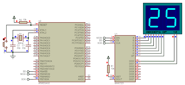
A master ATMega32 SPI could send data to many SPI slave devices on bus. MAX7221 is another example of an SPI slave device. MAX7221 is an 8-digit display driver. It could fit multiplexed seven-segment display, or a 8x8 dot matrix display. Both seven-segment and dot matrix display are common cathode. For more digits we can use a daisy-chain with preferred numbers of MAX7221. |
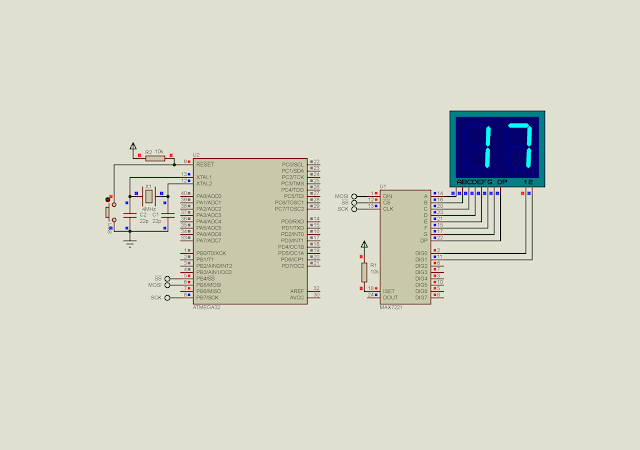
| A sample simulation of this example |
This device work independently. The master MCU configures and send the data only once. Then MAX7221 periodically displays and refresh by itself.
 |
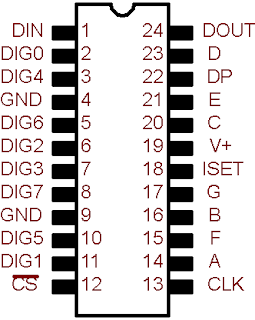
| MAX7221 28-DIP Package |
These are its pins description:
 |
| Pin description of MAX7221 |
The data for format for MAX7221 reception is 16-bit wise, and device into two 8-bit registers.
 |
| Command register uses only 4 lower nibble. |
I don't list all datasheet full specification here. I list only some needed technical details.
Every command register has its own address. We must load these address with any appropriate values.
 |
| MAX7221 Register Map |
These commands with value I selected:
- The 0x09 command register loads with 0xFF to enable BCD decoding for all digits.
- The 0x0B command register loads with 0x01 to limit the scanning for only digit 0 and 1.
- The 0x0C command register loads with 0x01 to turn on the device (called normal operation).
- The 0x0A command register loads with 0x09 to set the intensity to 10/16.
- All digits have its own command register ranges from 0x01 to 0x08. We load these command registers to display the value. The value could be a BCD format or anythings, up to the pre-setting.
In this example, I turn on only two digits. This two-digit display show the counting value at one second rate.
 |
| A sample of program |

code doesnt work in real life.
ReplyDeleteThis post was a delightful discovery! Your writing not only captures the essence of the topic but also makes it resonate on a personal level. The examples you chose were spot on, making the content both relatable and enlightening. Thanks for sharing your insights; I’m definitely bookmarking this for future reference!
ReplyDeleteLED Display Drivers
Enrgtech