In this module we have discuss about using ADC with some typical applications. Using a POT we can adjust the analog value fed to the ADC input pin manually and linearly. With this advantage we can use the ADC value to adjust the duty cycle of PWM signal.
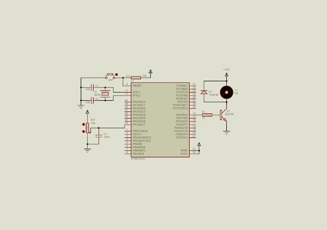
In this example, I use ADC to vary the PWM duty cycle between 0 to 100%. The ADC value is scaled from 1024 to 100 to fit the PWM timing. PWM signal is created by timer 0 interrupt. Each interrupt occurs for every 10 micro seconds.
Schematic diagram |
Source code:
#include <avr/io.h> #include "avr/interrupt.h" unsigned char cnt=0; void speedControl(unsigned int speed){ float _dutyCycle; unsigned int dutyCycle; _dutyCycle=speed*(100.0/1024); //dutyCycle=20; dutyCycle=10+(int)_dutyCycle; if(cnt<dutyCycle) PORTD|=(1<<0); if(cnt>=dutyCycle) PORTD&=~(1<<0); if(cnt>=100) cnt=0; } int main(void) { unsigned int adcResult; //PortD as output DDRD=0xFF; //PA0 or ADC0 as an analog input DDRA=0; //Set 1:8 pre-scaler TCCR0=0x02; //Clear overflow flag TIFR=0x01; //Enable Timer 0 interrupt TIMSK=0x01; //set global interrupt sei(); //Turn on the ADC module ADCSRA|=(1<<ADEN); /*Select ADC7*/ ADMUX|=0x07; while (1) { //Start the conversion ADCSRA|=(1<<ADSC); //Wait for the completion while((ADCSRA&(1<<ADSC))==1); //Read the result adcResult=ADCL+(ADCH<<8); speedControl(adcResult); } } ISR(TIMER0_OVF_vect){ //Load -5 to make 10 uS interrupt time TCNT0=-5; cnt+=1; TIFR=0x01; }
Click here to download its source file. Back to main tutorial page ATMega32 tutorials in C with Atmel Studio 7.
No comments:
Post a Comment