728x90

728x90

Saturday, August 8, 2020

Creating A Negative Voltage Regulator Using PIC16F818 PWM

Creating A Negative Voltage Regulator Using PIC16F818 PWM

 An Overview Of Negative Voltage Creating 

A negative voltage level is useful in some situations, a negative voltage reference for ADC module, a negative supply voltage for an op-amp. 
Creating A Negative Voltage Regulator Using PIC16F818 PWM
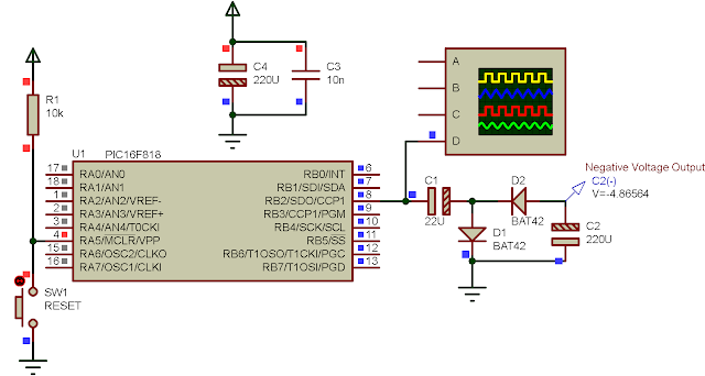
A simulation program sample

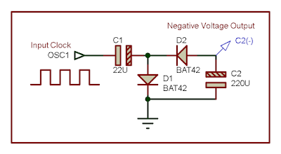
It's easily built using two high speed diodes, two polarized capacitor with an oscillator. An oscillator could be created with NE555 timer, or using an op-amp with some extra passive components.
Creating A Negative Voltage Regulator Using PIC16F818 PWM
A block of negative voltage generator. At the high cycle of OSC1, 
it charges the capacitor C1, and bypass D1 diode to the ground
creating a potential at both positive and negative pin of C1. 


Another option to create a negative voltage is using a DC-DC converter, as a case of using MC34063A. 

Using these two method as per above require an extra components placement on board. In any application where a microcontroller is needed, we can use a PWM signal created by the on-board microcontroller. Most 8-bit microcontroller, currently shipped with a PWM peripheral inside. If it isn't so, PWM signal could be created using software, by toggling an output pin with a specific period. 

PIC16F818 PWM Programming And Interfacing With CCS PICC
PIC16F818 is an 8-bit microcontroller. It's a tiny 18-pin available in DIP package. PWM signal is created by CCP1 module inside this device.

With the ease of complexity of programming, CCS PICC could configure the PWM output using a few line of code. Unlike other compiler, that a calculation to find PWM frequency and duty cycle is needed.

In CCS PICC, I use the #use pwm(options) directive to configure the module, frequency and duty cycle. But it's required to set the direction of CCP1 pin to an output direction. It's done within a few lines C code.

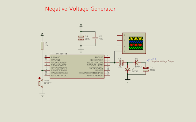
In this program, I use CCP1 of PIC16F818 to create PWM signal at the frequency of 1 kHz, and 50% duty cycle. This signal fed into the negative voltage generator circuit, creating a negative output voltage around -5 V, the same magnitude to the input voltage.

Creating A Negative Voltage Regulator Using PIC16F818 PWM
Schematic Diagram, excludes the supply voltage circuit for the MCU. CCP1 creates a PWM 
output at RB2. The MCU clock is internal 8 MHz RC oscillator inside.

C source code is just a dozen of lines.

#include<16F818.h>
#fuses INTRC_IO,NOWDT
#use delay(clock=8M)

/*Use CCP1 Module with the frequency of
1 kHz and 50% duty cycle*/
#use pwm(CCP1,FREQUENCY=1000,DUTY=50)

void main(void){
   output_B(0x00);
   set_tris_b(0x00);
   while(1){
   
   }
}

A screen shot of the running program shown below.

Creating A Negative Voltage Regulator Using PIC16F818 PWM
A simulation screen shot. Output voltage probe connects to C2(-). Output voltage 
reaches around -5 V when C2 is fully charged.

No comments:

Post a Comment

320x50

Search This Blog

tyro-728x90