Introduction
Timer/Counter1 module of ATMega32 is configurable to operate in fast Pulse Width Modulation (PWM) mode. There are two PWM blocks inside this module - PWM A and PWM B. Hence there are two corresponding output pins for these two blocks - OC1A and OC1B.
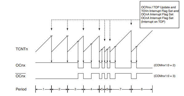
PWM output pulse has two mode, non-inverting and inverting mode. Its set and clear output pulse is the comparison between TCNT1 and OC1X register (OC1A or OC1B).
 |
| Fast PWM Mode - Timing Diagram |
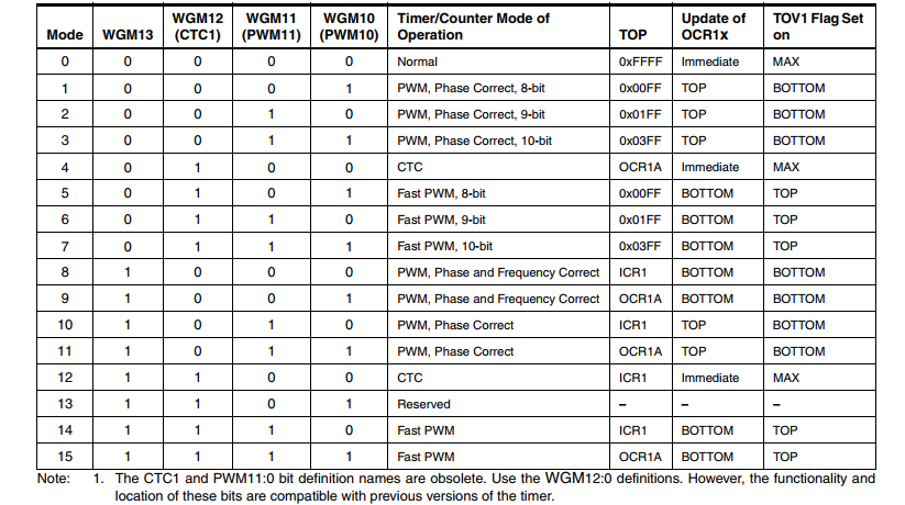
To make ATMega32 operates in this mode, user must set WGM13:0 of Timer/Counter1 Control Register (TCCR1x) to 5, 6, 7, 14, or 15. Its frequency is calculated as below.
 |
| Fast PWM Mode Frequency |
Its resolution is between 8 and 10-bit. Where,
 |
| Fast PWM Resolution |
Programming
- Timer/Counter1 Control Register A (TCCR1A)
 |
| TCCR1A |
This register contains some settings for fast PWM mode. Compare Output Mode bits used for selecting between inverting and non-inverting mode of fast PWM mode.
 |
| Compare Output Mode Bits of TCCR1A |
Waveform Generation Mode Bits must be set to any value as listed to make this module operates in fast PWM mode.
 |
| Waveform Generation Mode Bits |
- Timer/Counter1 Control Register B (TCCR1B)
 |
| TCCR1B |
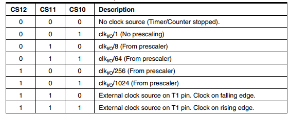
Clock Select Bits (CS12:10) allow user to set its prescaler effecting output frequency of fast PWM.
 |
| Clock Selection Bits |
- Output Compare Register A
 |
| Output Compare Register A |
 |
| Schematic Diagram |
Microcontroller clock is 16MHz from external crystal oscillator.
Click here to download archive.
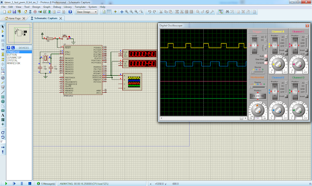
Now let use both of this PWM output of Timer/Counter1 module. Either OC1A and OC1B output signal are inverting with different duty cycle, but its frequency is unique.
 |
| Simulation screen shot |
Source code:
Click here to download this example.
No comments:
Post a Comment