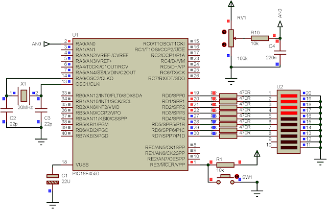
In the previous post, we show how to use ADC library function in CCS PICC. Here, the ADC is still in the discussion. In this example, I use almost the same source code, but one's difference is the output LED displays a bar graph pattern indicating the level of input voltage reading from the AN0.
00:00 / 00:00
ADC result is still 8-bit. This 8-bit result is scaled into an 9 number values correspond to 8 output LEDs on PORTD.
![]() |
LED bar graph running |
Source code from GitHub gist.
This file contains bidirectional Unicode text that may be interpreted or compiled differently than what appears below. To review, open the file in an editor that reveals hidden Unicode characters.
Learn more about bidirectional Unicode characters
#include<18f4550.h> | |
//Use High speed Crystal | |
#fuses HS | |
//Set the frequency for delay function | |
#use delay(clock=20M) | |
void main(void){ | |
unsigned int16 adcRead; | |
char ledBar[9]={0x00,0x01,0x03,0x07,0x0F,0x1F,0x3F,0x7F,0xFF}; | |
//RA0 As Input | |
set_tris_a(0x01); | |
//PORTD as output | |
set_tris_d(0x00); | |
//Set RA0 To Analog | |
setup_adc_ports(AN0); | |
//Select ADC internal RC Clock | |
setup_adc(ADC_CLOCK_INTERNAL); | |
//Select channel 0 for conversion | |
set_adc_channel(0); | |
while(1){ | |
adcRead=read_adc(); | |
//Wait for completion | |
while(!adc_done()); | |
adcRead=(adcRead*9)/256; | |
//Output the result to PORTD | |
output_D(ledBar[adcRead]); | |
delay_ms(50); | |
} | |
} |
Click here to download this example in zip file.
![]() |
Schematic Diagram |
Thanks for the tips guys. They were all great. I have been having issues with being fat both mentally and physically. Thanks to you guys i have been showing improvements. Do post more. Torchbeam
ReplyDeleteThanks for visiting my blog.
ReplyDelete