Saturday, July 9, 2022

Atmega32 Timer/Counter1 in Counter Mode

The Timer/Counter1 module of Atmega32 is able to count external pulse. It has a 16-bit counter/timer registers pair, TCNT1H and TCNT1L. We need to select its clock source of the Timer/Counter1 Control Register B - TCCR1B to allow this module working in external event counting mode. It work in two clock transitions, falling edge and rising edge. The clock source must be point to T1 (PB1) pin.
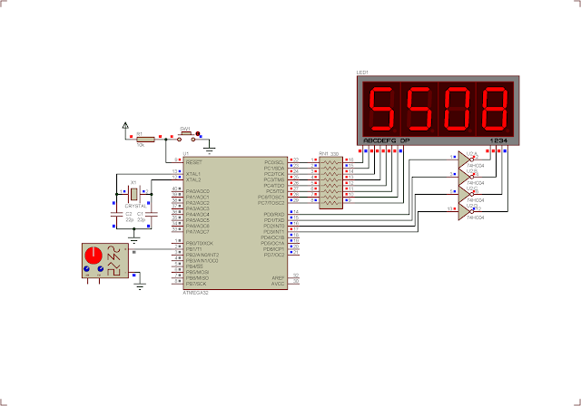
Atmega32 Timer/Counter1 in Counter Mode
Running program in Proteus Simulator

It also have a pre-scaler to divide a number of input clock pulse. Basically I will need only the TCCR1B, TCNT1H, and TCNT1L register to make this module operate in external counting mode.

  • Timer/Counter1 Control Register B - TCCR1B

Atmega32 Timer/Counter1 in Counter Mode

Timer/Counter1 Control Register B - TCCR1B

I need to select clock select bits to allow it to work in counter mode, with a rising edge of external clock.

Atmega32 Timer/Counter1 in Counter Mode
Clock Select Bit Description

I choose the "External clock source on T1 pin. Clock on rising edge". So CS12, CS11, and CS10 will set.

  • Timer/Counter1 - TCNT1H and TCNT1L Register 

Atmega32 Timer/Counter1 in Counter Mode
Timer/Counter1 – TCNT1H and TCNT1L Registers

This register composes of two 8-bit registers pair, TCNT1H and TCNT1L. They are readable and writable.

In this example, I make a counting system that could count up to 10000 before it rolls down. Since this register is 16-bit it maximum value is 65536 values. But it's not necessary here.

  1. /*
  2.  * m32Counter1MuxDisplay.c
  3.  *
  4.  * Created: 7/9/2022 6:10:41 PM
  5.  * Author : aki-technical
  6.  */
  7.  
  8. #include <avr/io.h>
  9.  
  10. #define F_CPU 4000000UL
  11. #include <util/delay.h>
  12.  
  13. int main(void)
  14. {
  15. int temp;
  16. /*Common Cathode Display*/
  17. unsigned char displayData[10]={0x3F,0x06,0x5B,0x4F,
    0x66,0x6D,0x7D,0x07,0x7F,0x6F};
  18. /*PortB and PortD Output*/
  19. DDRC=0xFF;
  20. DDRD=0xFF;
  21. /*Select T1 Clock in, rising edge*/
  22. TCCR1B|=(1<<CS12)|(1<<CS11)|(1<<CS10);
  23. /*Clear Timer/Counter1*/
  24. TCNT1H=0;
  25. TCNT1L=0;
  26. while (1)
  27. {
  28. /*Read the 16-bit counter registers*/
  29. temp=(TCNT1H<<8)+TCNT1L;
  30. /*Reset if it reaches 10000*/
  31. if (temp>9999)
  32. {
  33. temp=0;
  34. TCNT1H=0;
  35. TCNT1L=0;
  36. }
  37.  
  38. /*Display processing*/
  39. PORTD=0x00;
  40. PORTC=displayData[temp/1000];
  41. PORTD=0x01;
  42. _delay_ms(5);
  43.  
  44. PORTD=0x00;
  45. PORTC=displayData[(temp%1000)/100];
  46. PORTD=0x02;
  47. _delay_ms(5);
  48.  
  49. PORTD=0x00;
  50. PORTC=displayData[(temp%100)/10];
  51. PORTD=0x04;
  52. _delay_ms(5);
  53.  
  54. PORTD=0x00;
  55. PORTC=displayData[temp%10];
  56. PORTD=0x08;
  57. _delay_ms(5);
  58. }
  59. }
  60.  
  61.  

 Click here to download its source file.

Atmega32 Timer/Counter1 in Counter Mode
Schematic


No comments:

Post a Comment

Search This Blog

Labels

25AA010A (1) 8051 (7) 93AA46B (1) ADC (30) Analog Comparator (1) Arduino (15) ARM (6) AT89C52 (7) ATMega32 (54) AVR (57) CCS PICC (28) DAC (1) DHT11 (2) Display (105) Distance Sensor (3) DS18B20 (3) dsPIC (2) dsPIC30F1010 (2) EEPROM (5) Environment Sensor (4) esp8266 (1) I2C (29) Input/Output (67) Interrupt (19) Keil (5) Keypad (10) LCD (46) Master/Slave (1) MAX7221 (1) MCP23017 (5) MCP23S17 (4) Meter (3) MikroC (2) Motor (15) MPLABX (66) Nokia 5110 LCD (3) OLED (2) One-Wire (6) Oscillator (8) PCB (6) PCD8544 (3) PCF8574 (5) PIC (107) PIC12F (2) PIC16F628A (2) PIC16F630 (1) PIC16F716 (3) PIC16F818 (10) PIC16F818/819 (2) PIC16F84A (15) PIC16F876A (1) PIC16F877A (9) PIC16F88 (1) PIC16F887 (60) PIC18 (19) PIC18F1220 (4) PIC18F2550 (3) PIC18F4550 (12) PWM (11) RTC (8) Sensor (10) SH1106 (1) Shift Register (11) Shift Registers (2) SPI (24) STM32 (6) STM32 Blue Pill (6) STM32CubeIDE (6) STM32F103C8T6 (6) SysTick (3) temperature sensor (11) Thermometer (21) Timer/Counter (30) TM1637 (2) UART (7) Ultrasonic (4) Voltmeter (7) WDT (1) XC16 (2) XC8 (94)