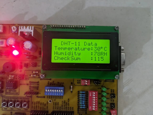
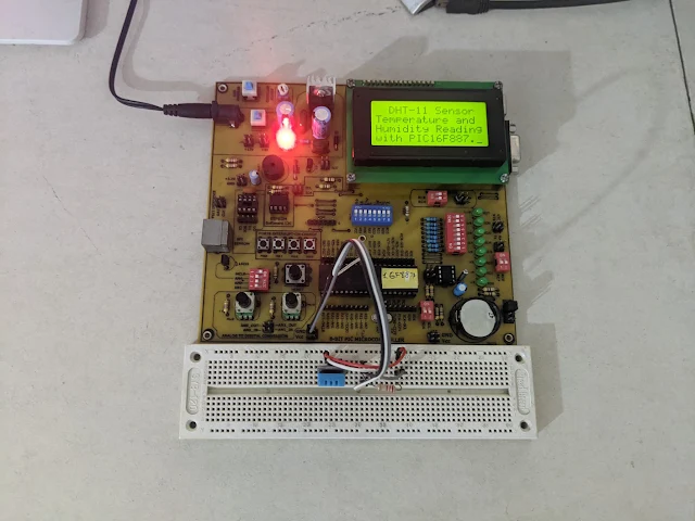
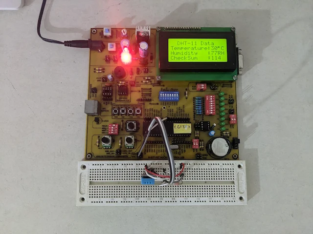
DHT11 converts the surrounding temperature and humidity to serial digital data for any micro-processor. It uses only one serial data wire. It able to convert between 0 and 50 degree Celsius in temperature, and 0 to 90RH for humidity. It's suitable for air conditioning system, agricultural application, etc.
DHT-11 Sensor |
Prototyping Board |
It contains 5 bytes (40 bits) of digital data. They are 1 byte of humidity, 1 byte of temperature, and 1 byte of check sum. For more information about decoding its data byte please check this post.
DTH-11 Sensor |
TC1604A-01 16x4 Character LCD Module |
In this example, I use an 8-bit PIC micro-controller PIC16F887, a DHT-11 sensor module, and a 16x2 character LCD to read and display the environmental data. I use the Microchip MPLABX IDE v6.15 and its XC8 C compiler v2.36 (free version).
/* * File: main.c * Author: Admin * * Created on December 26, 2023, 9:03 PM * PIC16F887 DHT-11 Sensor and LCD Example * MPLABX IDE v6.15 XC8 v2.36 */ #include <xc.h> #include "config.h" #include "LCD4Bits.h" #include <stdio.h> #define _XTAL_FREQ 8000000UL #define DATA_PIN RD0 #define DATA_DIR TRISD0 uint8_t data[5]; void readDHT11(void){ for(uint8_t i=0;i<5;i++) data[i]=0; DATA_DIR=0; DATA_PIN=1; __delay_ms(10); DATA_PIN=0; __delay_ms(18); DATA_PIN=1; __delay_us(30); DATA_PIN=0; DATA_DIR=1; __delay_us(10); while(DATA_PIN==0); __delay_us(10); while(DATA_PIN==1); __delay_us(10); //Start of Transmission for(uint8_t i=0;i<5;i++) { for(uint8_t j=0;j<8;j++){ __delay_us(5); while(DATA_PIN==0); __delay_us(50); if(DATA_PIN==1) { data[i]|=(1<<7-j); while(DATA_PIN==1);} } __delay_us(10); } /*CRC Calculation - the last byte data[4] is check sum*/ uint8_t crc = data[0]+data[1]+data[2]+data[3]; if(crc!=data[4]) {for(uint8_t i=0;i<4;i++) data[i]=0; return;} __delay_us(10); } void main(void) { OSCCONbits.IRCF=7; char msg[8]; PORTA=0; TRISA=0; lcdInit(); lcdString("Temperature:"); __delay_ms(1000); while(1){ readDHT11(); sprintf(msg,"%2dRH",data[0]); lcdXY(1,2); lcdString(msg); sprintf(msg,"%2d%cC",data[2],223); lcdXY(8,2); lcdString(msg); __delay_ms(500); } return; }
I use its 8MHz internal oscillator clock source leaving the XTAL1 and XTAL2 pin opened.
Dashboard |
Running Program |
Running Program |
Simulating Program |
Proteus VSM can be used for circuit design and simulation. Click here to download its source file.
No comments:
Post a Comment