Overview of I2C
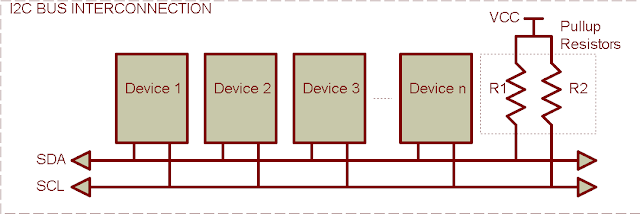
The I2C (Inter-Integrated Circuit) is a low speed communication bus allowing many device connected. I2C use only two bi-directional wires known as SDA (Serial Data) and SCL (Serial Clock). SCL synchronizes the data SDA between devices. These two lines are paired together. This communication protocol work fine in short wire range, or on-board device inter-connect. Commonly known I2C devices are, RTC, EEPROM and Input/Output Expanding etc. |
| DS1307 RTC and Atmel 24C16 EEPROM |
I2C was developed by Phillip, but currently it has been using by many vendors. For Atmel MCU, I2C names as TWI (Two-Wire Serial Interface).

Both SDA and SCL are open-drain or open-collector. Each requires a pullup resistor about 4.7 k Ohm. Some device speeds up to 400 kHz.
On this bus, it needs at least a master I2C device. A master I2C initiates and terminates a transmission. A slave I2C device (node) addressed by a master.
Data Transmission
- Bits Transfer
Each data bit is transfer at every high logic level of SCL line, except the start and stop conditions.
- START and STOP Conditions
On the I2C bus, a master begins and ends the transmission. A START condition is created by a master to begin the transmission. The transmission is ended when a master creates a STOP condition. During these two condition, the bus is called busy.
A REPEATED START condition is a START condition created between both START and STOP contdition. It's the same to START condition. But the transmision is ended with the STOP condition.
- The Address Packet
Transmitted address packet of I2C on the bus is 9-bit long, in which:
- 7-bit address
- 1-bit read/write (R/W)
- 1-bit Acknowledge (ACK)
The 7-bit address is defined by the device datasheet, R/W bit command the slave device to write data or address into otherwise reading the data out. Acknowledge bit is a flag used by the slave, commanding the master that it's correctly addressed. When the reception is done, the receiver (slave) pulls SDA low at the ninth clock pulse of SCL.
- The Data Packet
Data transmit on the I2C bus is 9-bit long, plus one acknowledge (ACK) bit. On the successful reception, the receiver pull the SDA low at the ninth SCL clock cycle.
- Transmission
An I2C transmission must contain the followings:
I2C Example
PIC16F887
In the following examples, I use the PIC16F887 and MPLABX IDE with XC8 C compiler to program the I2C module.
- PIC16F887 I2C DS1307 RTC LCD Using XC8
- PIC16F887 I2C AT24C16B EEPROM LCD Using XC8
- PIC16F887 SH1106 I2C OLED Display Example using XC8
- PIC16F887 TM1637 Six Digits 7-Segment Display Example Using XC8
- PIC16F887 TM1637 Display and Key Scan Example using XC8
- PIC16F887 PCF8574 I2C Example using XC8
- PIC16F887 KeyPad and Character LCD Example using XC8
- PIC16F887 PCF8574AP I2C 4x4 KeyPad using XC8
- PIC16F887 PCF8574AP I2C LCD Example using XC8
- PIC16F887 MCP23017 I2C GPIO Example using XC8
- PIC16F887 MCP23017 Key Pad and 7-Segment Display Example using XC8
- PIC16F887 MCP23017 I2C LCD Example using XC8
- PIC16F887 MCP23017 LCD and Keypad Interfacing using XC8


No comments:
Post a Comment