Wednesday, January 3, 2024

PIC16F887 I2C DS1307 RTC LCD Using XC8

Overview

PIC16F887 has a Master Synchronous Serial Port (MSSP) module that's useful for communicating with other serial interface peripheral or micro-controller devices. These peripheral devices may be Serial EEPROMs, shift registers, display drivers, A/D converters, etc. The MSSP module can operate in one of two modes:

  • Serial Peripheral Interface (SPI)
  • Inter-Integrated Circuit (I2C)
  •  Full Master mode
  •  Slave mode (with general address call).

The I2C interface supports the following modes in hardware:

  • Master mode
  • Multi-Master mode
  • Slave mode.

In this example, I picking up the I2C mode of this communication module. Inter Integrated Circuit (I2C) is a two wire communication interface developed by Phillip. It's useful for communicating with other peripheral such as serial EEPROM, Real Time Clock (RTC), I/O expanding, sensor, or even other micro-controllers.
PIC16F887 I2C DS1307 RTC LCD Using XC8
Running Program


Operation Modes

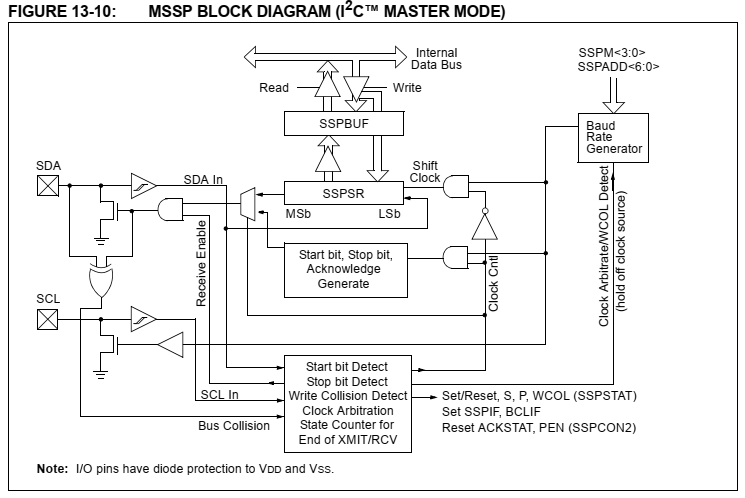
Master mode is common for interfacing with other on board peripheral. PIC16F887 uses two wires to transmit data serially, SDA(RC4) and SCL(RC3).
PIC16F887 I2C DS1307 RTC LCD Using XC8
Master Mode Block Diagram

The Baud Rate Generator used for the SPI mode operation is now used to set the SCL clock frequency for either 100 kHz, 400 kHz, or 1 MHz I2C operation.The Baud Rate Generator reload value is contained in the lower 7 bits of the SSPADD register. 

In master mode we will need to use these MSSP registers,

MSSP Control Register 1 (SSPCON)
MSSP Control Register 2 (SSPCON2)
MSSP STATUS register (SSPSTAT)
Serial Receive/Transmit Buffer (SSPBUF)
MSSP Address register (SSPADD)

There are also two peripheral interrupt registers PIR1 and PIE1. 

A typical transmit sequence would go as follows:

a- The user generates a Start condition by setting the Start Enable (SEN) bit (SSPCON2 register).
b- SSPIF is set. The MSSP module will wait the required start time before any other operation
takes place.
c- The user loads the SSPBUF with the address to transmit.
d- Address is shifted out the SDA pin until all eight bits are transmitted.
e- The MSSP module shifts in the ACK bit from the slave device and writes its value into the
ACKSTAT bit (SSPCON2 register).
f- The MSSP module generates an interrupt at the end of the ninth clock cycle by setting the SSPIF bit.
g- The user loads the SSPBUF with eight bits of data.
h- Data is shifted out the SDA pin until all eight bits are transmitted.
i- The MSSP module shifts in the ACK bit from the slave device and writes its value into the
ACKSTAT bit (SSPCON2 register).
j- The MSSP module generates an interrupt at the end of the ninth clock cycle by setting the SSPIF bit.
k- The user generates a Stop condition by setting the Stop Enable bit PEN (SSPCON2 register).
l- Interrupt is generated once the Stop condition is complete. 

DS1307 RTC

The DS1307 serial real-time clock (RTC) is a lowpower, full binary-coded decimal (BCD) clock/calendar plus 56 bytes of NV SRAM. Address and data are transferred serially through an I2C, bidirectional bus. The clock/calendar provides seconds, minutes, hours, day, date, month, and year information. The end of the month date is automatically adjusted for months
with fewer than 31 days, including corrections for leap year. The clock operates in either the 24-hour or 12- hour format with AM/PM indicator. The DS1307 has a built-in power-sense circuit that detects power failures and automatically switches to the backup supply.
Timekeeping operation continues while the part operates from the backup supply.
PIC16F887 I2C DS1307 RTC LCD Using XC8
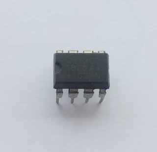
DS1307 I2C RTC 8-PIN DIP


PIC16F887 I2C DS1307 RTC LCD Using XC8
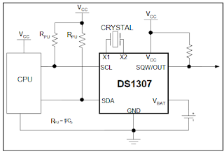
Typical Operating Circuit

PIC16F887 I2C DS1307 RTC LCD Using XC8
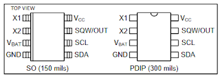
PIN CONFIGURATIONS

PIC16F887 I2C DS1307 RTC LCD Using XC8
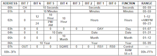
Timekeeper Registers

Data Read—Slave Transmitter Mode
PIC16F887 I2C DS1307 RTC LCD Using XC8
Data Read—Slave Transmitter Mode


We 0xD0 for address write, and 0xD1 for address read. 

MPLABX IDE and XC8 Programming

Using C compiler is very common for most of small 8-bit micro-controller now. XC8 has free version of C compiler for 8-bit PIC micro-controller.

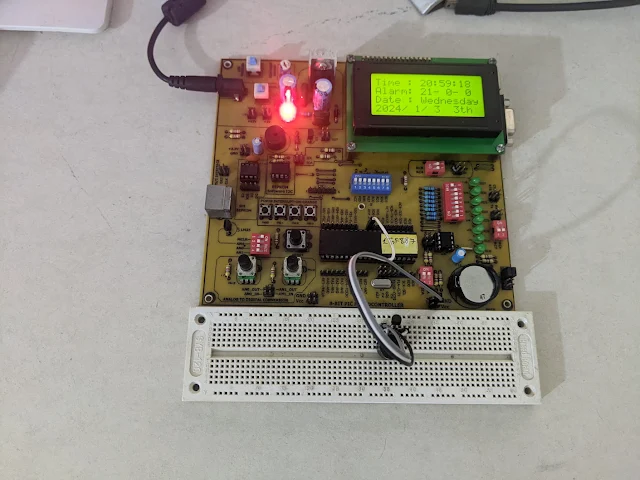
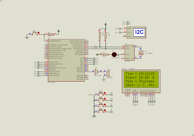
In this example, I use a PIC16F887, a 20x4 character LCD, a DS1307 RTC, an alarm buzzer, four input buttons, etc. The program display current time, date, and alarm information. It also allow us to adjust these parameters manually using push buttons.

  1. /*
  2.  * File: main.c
  3.  * Author: Admin
  4.  *
  5.  * Created on January 2, 2024, 2:37 PM
  6.  */
  7.  
  8. #include <xc.h>
  9. #include "config.h"
  10. #include "i2c.h"
  11. #include "lcd.h"
  12. #include <stdio.h>
  13.  
  14. //__EEPROM_DATA(0,28,15,0,0,0,0,0);
  15.  
  16. const char ds1307_write = 0xD0;
  17. const char ds1307_read = 0xD1;
  18.  
  19. char msg[16],_rtc[7],_alarm[3],_match=0;
  20.  
  21. uint8_t bcd2dec(uint8_t data){
  22. return (data>>4)*10+(data&0x0F);
  23. }
  24. uint8_t dec2bcd(uint8_t data){
  25. return ((data/10)<<4)+(data%10);
  26. }
  27.  
  28. void day_of_week(char _day){
  29. lcdXY(1,3); lcdString("Date : ");
  30. switch(_day){
  31. case 1: lcdString("Monday"); break;
  32. case 2: lcdString("Tuesday"); break;
  33. case 3: lcdString("Wednesday"); break;
  34. case 4: lcdString("Thursday"); break;
  35. case 5: lcdString("Friday"); break;
  36. case 6: lcdString("Saturday"); break;
  37. case 7: lcdString("Sunday"); break;
  38. }
  39. }
  40.  
  41. uint8_t setting=0;
  42. void __interrupt() MY_ISR(void){
  43. if(RBIF){
  44. if(RB0==0){
  45. setting++;
  46. }
  47. if(RB1==0){
  48. if(setting==1){
  49. _rtc[2]=bcd2dec(_rtc[2]);
  50. _rtc[2]++;
  51. if(_rtc[2]>0x23) _rtc[2]=0;
  52. _rtc[2]=dec2bcd(_rtc[2]);
  53. i2c_start();
  54. i2c_write(ds1307_write);
  55. i2c_write(2);
  56. i2c_write(_rtc[2]);
  57. i2c_stop();
  58. }
  59. if(setting==2){
  60. _alarm[2]=bcd2dec(_alarm[2]);
  61. _alarm[2]++;
  62. if(_alarm[2]>23) _alarm[2]=0;
  63. EEPROM_WRITE(2,_alarm[2]);
  64. while(RW);
  65. _alarm[2]=dec2bcd(_alarm[2]);
  66. }
  67. if(setting==3){
  68. _rtc[6]=bcd2dec(_rtc[6]);
  69. _rtc[6]++;
  70. if(_rtc[6]>99) _rtc[6]=0;
  71. _rtc[6]=dec2bcd(_rtc[6]);
  72. i2c_start();
  73. i2c_write(ds1307_write);
  74. i2c_write(6);
  75. i2c_write(_rtc[6]);
  76. i2c_stop();
  77. }
  78. if(setting==4){
  79. _rtc[3]++;
  80. if(_rtc[3]>0x07) _rtc[3]=0;
  81. i2c_start();
  82. i2c_write(ds1307_write);
  83. i2c_write(3);
  84. i2c_write(_rtc[3]);
  85. i2c_stop();
  86. }
  87. }
  88. if(RB2==0){
  89. if(setting==1){
  90. _rtc[1]=bcd2dec(_rtc[1]);
  91. _rtc[1]++;
  92. if(_rtc[1]>0x59) _rtc[1]=0;
  93. _rtc[1]=dec2bcd(_rtc[1]);
  94. i2c_start();
  95. i2c_write(ds1307_write);
  96. i2c_write(1);
  97. i2c_write(_rtc[1]);
  98. i2c_stop();
  99. }
  100. if(setting==2){
  101. _alarm[1]=bcd2dec(_alarm[1]);
  102. _alarm[1]++;
  103. if(_alarm[1]>59) _alarm[1]=0;
  104. EEPROM_WRITE(1,_alarm[1]);
  105. while(RW);
  106. _alarm[1]=dec2bcd(_alarm[1]);
  107. }
  108. if(setting==3){
  109. _rtc[5]=bcd2dec(_rtc[5]);
  110. _rtc[5]++;
  111. if(_rtc[5]>0x12) _rtc[5]=1;
  112. _rtc[5]=dec2bcd(_rtc[5]);
  113. i2c_start();
  114. i2c_write(ds1307_write);
  115. i2c_write(5);
  116. i2c_write(_rtc[5]);
  117. i2c_stop();
  118. }
  119. }
  120. if(RB3==0){
  121. if(setting==1){
  122. _rtc[0]=bcd2dec(_rtc[0]);
  123. _rtc[0]++;
  124. if(_rtc[0]>0x59) _rtc[0]=0;
  125. _rtc[0]=dec2bcd(_rtc[0]);
  126. i2c_start();
  127. i2c_write(ds1307_write);
  128. i2c_write(0);
  129. i2c_write(_rtc[0]);
  130. i2c_stop();
  131. }
  132. if(setting==2){
  133. _alarm[0]=bcd2dec(_alarm[0]);
  134. _alarm[0]++;
  135. if(_alarm[0]>59) _alarm[0]=0;
  136. EEPROM_WRITE(0,_alarm[0]);
  137. while(RW);
  138. _alarm[0]=dec2bcd(_alarm[0]);
  139. }
  140. if(setting==3){
  141. _rtc[4]=bcd2dec(_rtc[4]);
  142. _rtc[4]++;
  143. if(_rtc[4]>0x31) _rtc[4]=1;
  144. _rtc[4]=dec2bcd(_rtc[4]);
  145. i2c_start();
  146. i2c_write(ds1307_write);
  147. i2c_write(4);
  148. i2c_write(_rtc[4]);
  149. i2c_stop();
  150. }
  151. }
  152. RBIF=0;
  153. __delay_ms(200);
  154. }
  155. if(setting>4) {
  156. setting=0;
  157. lcdCommand(0x01);
  158. __delay_ms(5);
  159. }
  160. }
  161. void main(void) {
  162. OSCCONbits.IRCF=7;
  163.  
  164. _alarm[2]=dec2bcd(EEPROM_READ(2));
  165. _alarm[1]=dec2bcd(EEPROM_READ(1));
  166. _alarm[0]=dec2bcd(EEPROM_READ(0));
  167. lcdInit();
  168. TRISD7=0;
  169. i2c_init(100000);
  170. PORTB=0;
  171. TRISB=0x0F;
  172. OPTION_REGbits.nRBPU=0;
  173. WPUB=0x0F;
  174. IOCB=0x0F;
  175. INTCONbits.RBIE=1;
  176. INTCONbits.RBIF=0;
  177. INTCONbits.GIE=1;
  178. lcdCommand(0x0C);
  179. __delay_ms(5);
  180.  
  181. while(1){
  182. for(char i=0;i<7;i++){
  183. i2c_start();
  184. i2c_write(ds1307_write);
  185. i2c_write(i);
  186. i2c_stop();
  187. __delay_us(100);
  188.  
  189. i2c_start();
  190. i2c_write(ds1307_read);
  191. _rtc[i]=i2c_read(0);
  192. i2c_stop();
  193. __delay_us(100);
  194. }
  195. sprintf(msg,"Time : %2d:%2d:%2d",
  196. bcd2dec(_rtc[2]),bcd2dec(_rtc[1]),bcd2dec(_rtc[0]));
  197. lcdXY(1,1); lcdString(msg);
  198. sprintf(msg,"Alarm: %2d-%2d-%2d",
  199. bcd2dec(_alarm[2]),bcd2dec(_alarm[1]),bcd2dec(_alarm[0]));
  200. lcdXY(1,2); lcdString(msg);
  201. sprintf(msg,"20%2d/%2d/%2d %dth",
  202. bcd2dec(_rtc[6]),bcd2dec(_rtc[5]),bcd2dec(_rtc[4]),bcd2dec(_rtc[3]));
  203. lcdXY(1,4); lcdString(msg);
  204. day_of_week(_rtc[3]);
  205. for(char i=0;i<3;i++){
  206. if((_alarm[i]-_rtc[i])==0) _match++;
  207. }
  208. if(_match==3){
  209. RD7=1;
  210. __delay_ms(5000);
  211.  
  212. }else RD7=0;
  213. _match=0;
  214.  
  215. switch(setting){
  216. case 1: lcdXY(16,1); lcdData('<'); break;
  217. case 2: lcdXY(16,2); lcdData('<'); break;
  218. case 3: lcdXY(16,3); lcdData('<'); break;
  219. case 4: lcdXY(16,4); lcdData('<'); break;
  220. }
  221. __delay_ms(500);
  222. }
  223. return;
  224. }
  225.  

I use my own test board to run this program. A PICKit2 programmer still support this chip.
PIC16F887 I2C DS1307 RTC LCD Using XC8

Proteus Simulation


No comments:

Post a Comment

Search This Blog

Labels

25AA010A (1) 8051 (7) 93AA46B (1) ADC (30) Analog Comparator (1) Arduino (15) ARM (6) AT89C52 (7) ATMega32 (56) AVR (57) CCS PICC (28) DAC (1) DHT11 (2) Display (105) Distance Sensor (3) DS18B20 (3) dsPIC (2) dsPIC30F1010 (2) EEPROM (5) Environment Sensor (4) esp8266 (1) I2C (29) Input/Output (67) Interrupt (19) Keil (5) Keypad (10) LCD (47) Master/Slave (1) MAX7221 (1) MCP23017 (5) MCP23S17 (4) Meter (3) MikroC (2) Motor (15) MPLABX (71) Nokia 5110 LCD (3) OLED (2) One-Wire (6) Oscillator (8) PCB (6) PCD8544 (3) PCF8574 (5) PIC (107) PIC12F (2) PIC16F628A (2) PIC16F630 (1) PIC16F716 (3) PIC16F818 (10) PIC16F818/819 (2) PIC16F84A (15) PIC16F876A (1) PIC16F877A (9) PIC16F88 (1) PIC16F887 (60) PIC18 (19) PIC18F1220 (4) PIC18F2550 (3) PIC18F4550 (12) PWM (11) RTC (8) Sensor (10) SH1106 (1) Shift Register (11) Shift Registers (3) SPI (24) STM32 (6) STM32 Blue Pill (6) STM32CubeIDE (6) STM32F103C8T6 (6) SysTick (3) temperature sensor (11) Thermometer (21) Timer/Counter (31) TM1637 (2) UART (7) Ultrasonic (4) Voltmeter (7) WDT (1) XC16 (2) XC8 (94)