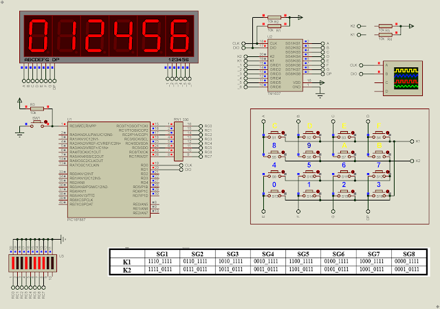
In previous post, we use TM1637 to display 7-Segment data. This chip has a 8x2 key scan circuit, giving a 16 different key value. This advantage is suitable for most of household electronics appliances, washing machine, induction cooker, micro-wave oven, etc.
 |
| Simulating Program |
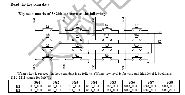
To read key, the micro-processor must send the read key scan data command (0x42), follows by one more start command, and the process the serial data input receiving. Least Significant Bit (LSB) is received first. However received key scan data is in reverse direction. So the we need to re-arrange it, or process the receiving data using MSB first. For example, the key value of "1110_1111" is equal to 0xF7 (1111_0111).
 |
| Key Scan Diagram |
 |
| Address Command Setting |
In this example, the program keeps scanning and receiving key scan data. It will show on the 7-Segmen display one by one, right to left.
The clock frequency must not exceed 250kHz. I wrote my own driver with some idea from other GitHub users. Most of libraries for this chip are design to run on Arduino.
Click here to download its source file.
No comments:
Post a Comment